Non-contact vehicle measurement method and system
a technology of non-contact vehicles and measurement methods, applied in measurement devices, instruments, surveying and navigation, etc., can solve the problems of increasing system costs, increasing system costs, and increasing the complexity of inventory managemen
- Summary
- Abstract
- Description
- Claims
- Application Information
AI Technical Summary
Benefits of technology
Problems solved by technology
Method used
Image

Examples
embodiment 1
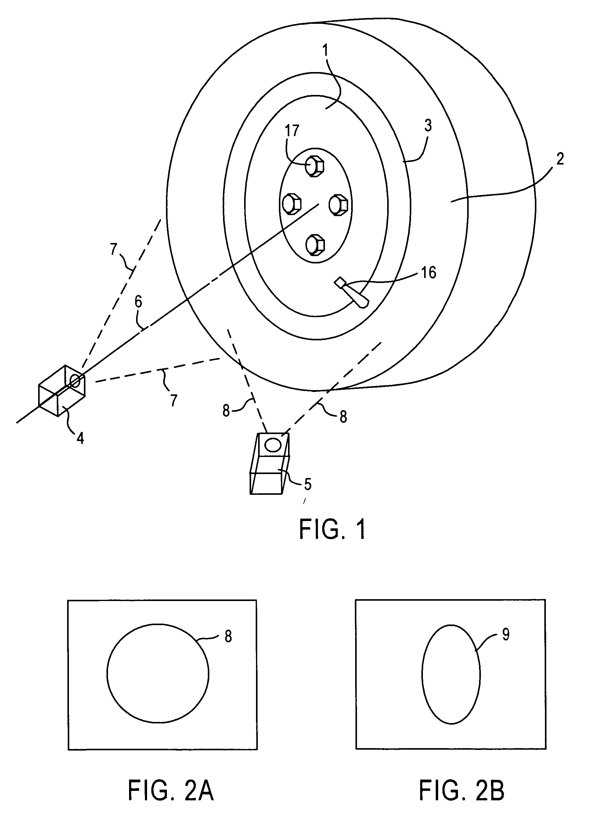
[0036]FIG. 1 shows an exemplary non-contact measurement system for measuring spatial parameters related to a wheel without the assistance from a target with known target patterns, or attachments or markings on the wheel, or pre-known features of the wheel. As shown in FIG. 1, a wheel 1 having a mounted tire 2 (collectively “wheel assembly”) is provided for measurements. Two cameras 4 and 5 are provided to view the wheel assembly, or a portion thereof. The cameras are used to provide data for imaging metrology, such as CCD or CMOS cameras. Each of the cameras has a field of view noted by dashed lines 7 and 8, respectively. The positional relationship between cameras 4 and 5 is known and / or predetermined, and is chosen so that the images of the rim circle, shown in FIGS. 2A and 2B, are sufficiently different to allow calculation of interface 3, between the sidewall of the tire and the edge of the rim on which the tire is mounted, relative to the cameras. In one embodiment, only one ca...
embodiment 2
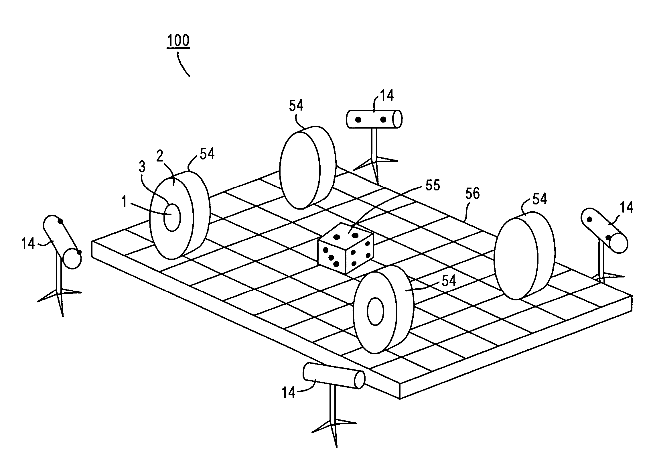
[0074] One application of the exemplary non-contact measurement system is to determine wheel alignment parameters of a vehicle, such as toe, camber, caster, etc. FIG. 5 shows an exemplary alignment system using non-contact measurements as described above. For each wheel 54, a measurement pod 14 is provided. Measurement pod 14 includes two cameras having a known positional relationship relative to each other. The cameras are configured to capture images of the wheels. Measurement pods are placed in close proximity to wheels 54 to obtain clear images of tire 1, mounting wheel 2 and edge 3 on wheel 54. The alignment system further includes a data processing system, such as a computer, that receives, or has access to, the images captured by the cameras.
[0075] A calibration process is performed to determine relative positions and angles between measurement pods 14. During the calibration process, a known object with known geometrical characteristics is provided to be viewed by each meas...
embodiment 3
[0079]FIG. 6 shows another exemplary measurement system that embodies non-contact measurements using a different calibration approach. Multiple measurement pods 14A-14D are used to obtain images of vehicle wheels 54. Each measurement pod includes at least one imaging device for producing at least two images of a wheel. For example, each measurement pod includes two measurement cameras arranged in a known positional relationship relative to each other. Similar to embodiments described above, the system further includes a data processing system, such as a computer, that receives, or has access to, images captured by the measurement pods.
[0080] Each measurement pod further includes calibrations devices for determining relative positions between the measurement modules. For instance, measurement pod 14A includes a calibration target 58 and a calibration camera 57. Calibration camera 57 is used to view a calibration target 58 of another measurement pod 14B, and calibration target 58 on ...
PUM
 Abstract
Description
Claims
Application Information
 - R&D
- Intellectual Property
- Life Sciences
- Materials
- Tech Scout
- Unparalleled Data Quality
- Higher Quality Content
- 60% Fewer Hallucinations
Browse by: Latest US Patents, China's latest patents, Technical Efficacy Thesaurus, Application Domain, Technology Topic, Popular Technical Reports.
© 2025 PatSnap. All rights reserved.Legal|Privacy policy|Modern Slavery Act Transparency Statement|Sitemap|About US| Contact US: help@patsnap.com