Valve stem having a reverse taper

a valve stem and taper technology, applied in the field of injection molding, can solve the problems of improper gate vestiges, plastic in the gate area solidifying, and difficulty in creating solidification or plugs in the gate area

Inactive Publication Date: 2006-07-13
HUSKY INJECTION MOLDING SYST LTD
View PDF12 Cites 37 Cited by
  • Summary
  • Abstract
  • Description
  • Claims
  • Application Information

AI Technical Summary

Problems solved by technology

However, the plastic in the gate area solidifies because the surrounding area is not sufficiently heated to maintain the liquid or molten state.
One of the problems with thermal gates is the difficulty creating the solidification or plug in the gate area.
Another problem with thermal gates is improper gate vestiges.
The major problem with the devices known in the prior art is leakage or weepage of molten plastic in clearance areas between the valve stem, and the manifold bushing or valve bushing when the valve stem is in the up or open position.
Unfortunately, the devices known in the prior art do not effectively seal the clearance area between the valve stem and the manifold bushing or valve bushing when the valve stem is in the up or open position.
Leakage or weepage is so common that some devices in the prior art have leakage or weepage holes to direct leakage or weepage away from critical areas of the hot runner system.
Unfortunately, utilizing leakage or weepage holes is not desirable and leakage or weepage holes can only accommodate a certain quantity of leakage or weepage.
Leakage or weepage

Method used


Image

  • Valve stem having a reverse taper
  • Valve stem having a reverse taper
  • Valve stem having a reverse taper

Examples


Embodiment Construction

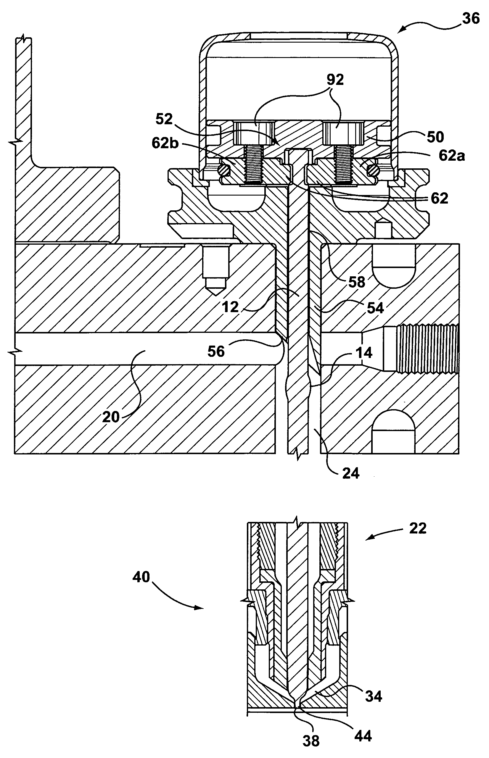
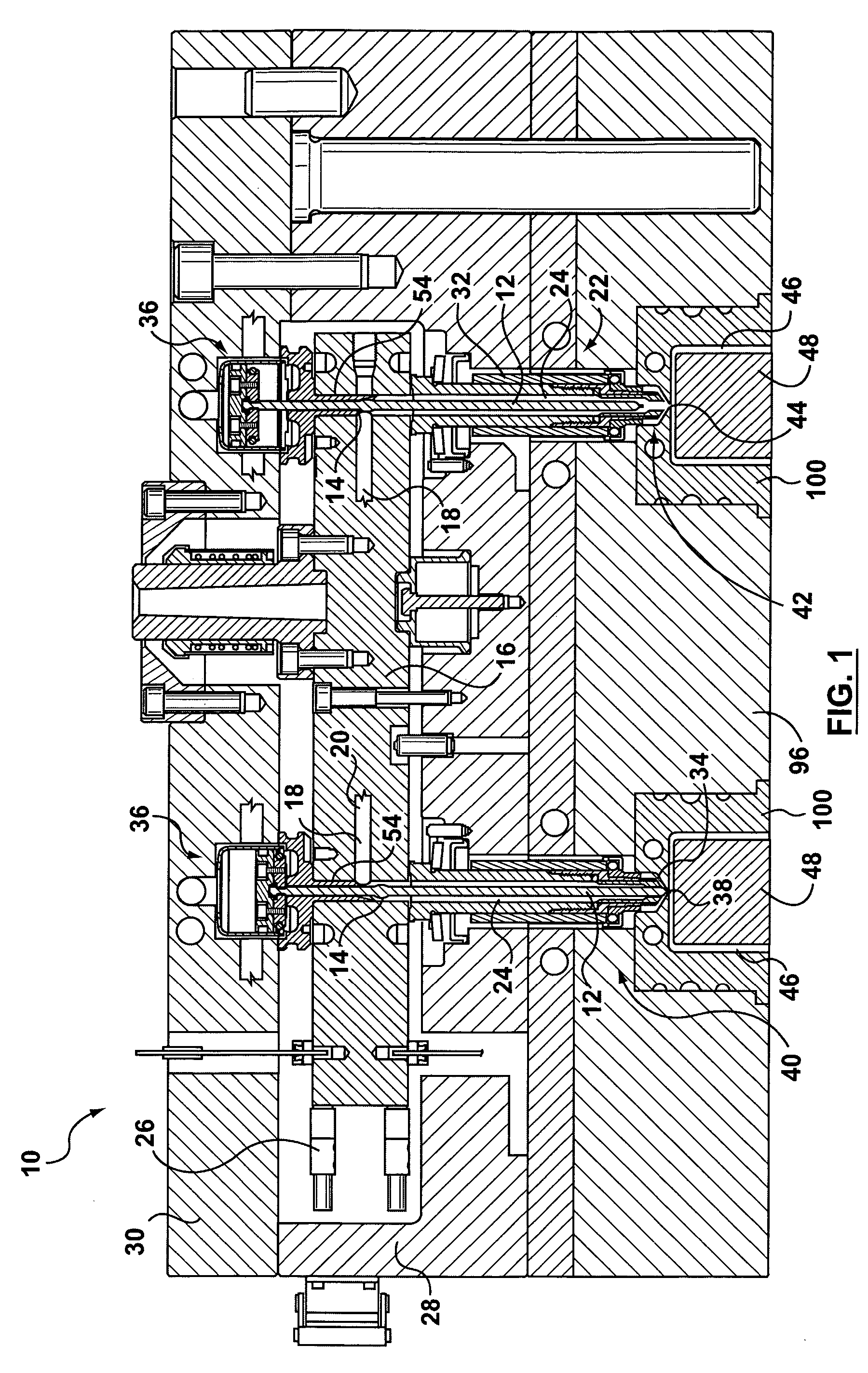
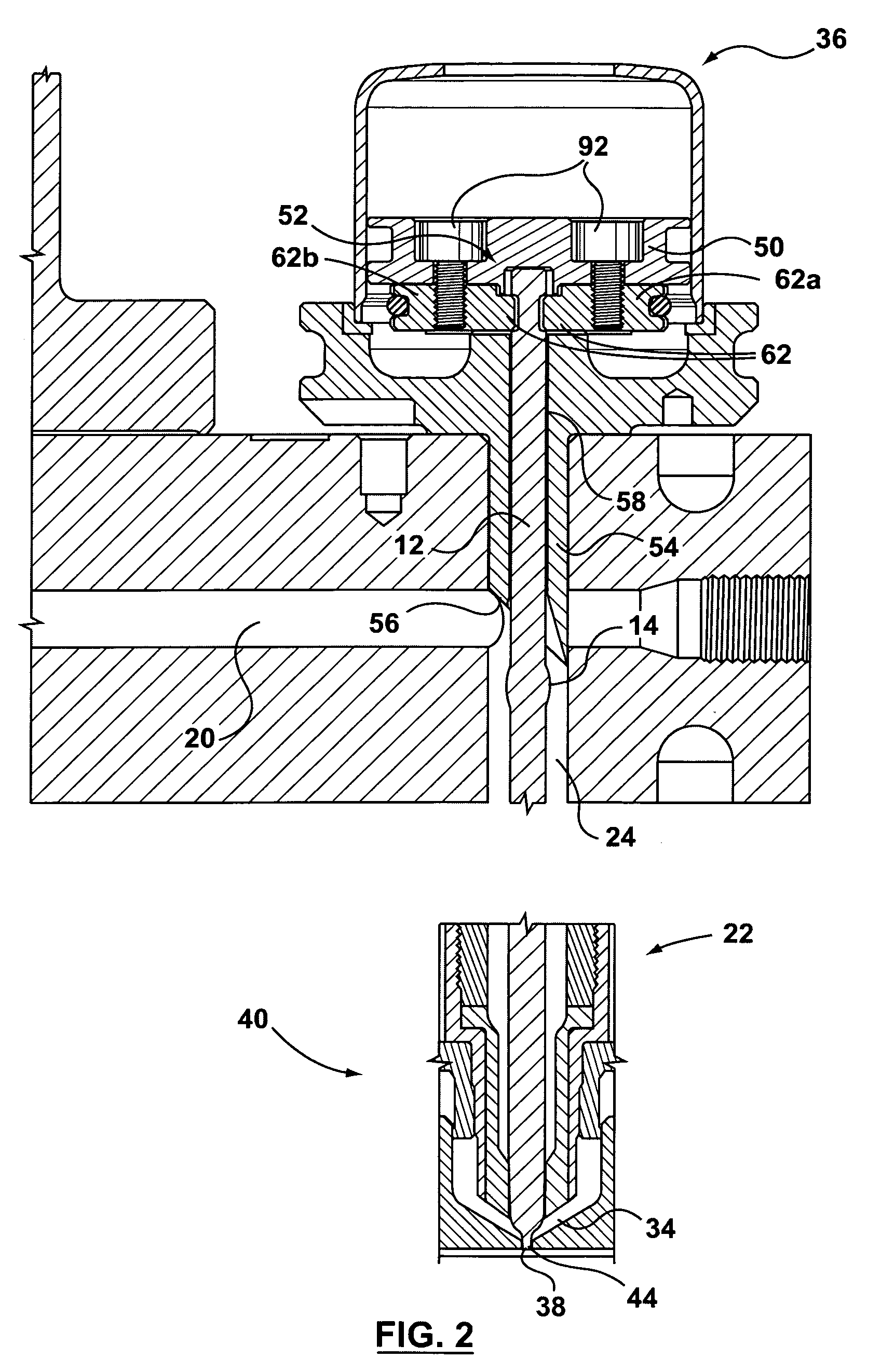
[0030] Referring now to the drawings and initially to FIG. 1, a hot runner system 10 having valve stems 12 with reverse tapers 14 thereon is shown in accordance with the present invention. The number of valve stems 12, etc. may be varied and is not meant to be limiting. The following description is not intended to describe each and every part of the hot runner system 10; rather, it describes the parts necessary to understand and practice the present invention.

[0031] The hot runner system 10 is used to transfer molten plastic from an injector (not shown) to at least one mold cavity 46 in a pair of cooperating mold plates 48, 100. The hot runner system 10 includes a manifold 16 having internal flow channels 18 for distributing molten plastic 20 to internal flow channels 24 of nozzles 22. The manifold 16 is operatively mounted between a manifold plate 28 and a backing plate 30. To maintain the molten plastic 20 in liquid form, the manifold 16 is heated by a manifold heater 26.

[0032] ...


PUM

PropertyMeasurementUnit
Diameteraaaaaaaaaa

Abstract

A valve stem has a reverse taper thereon used in an injection nozzle for a hot runner system. The valve stem is moved downward into a closed position, such that a valve stem tip plugs or blocks an opening in a gate area, thereby precluding molten plastic from exiting the injection nozzle. The valve stem is moved upward into an open position, thereby allowing molten plastic to flow from the injection nozzle. In the open position, the reverse taper seals a clearance between the valve stem and either a manifold bushing or valve bushing, thereby precluding stem leakage or weepage. The reverse taper has a diameter which is larger than an internal diameter of internal passage of the valve bushing or manifold bushing. The valve stem also includes a headless end.

Description

BACKGROUND OF THE INVENTION [0001] 1. Technical Field of the Invention [0002] The present invention relates to injection molding and more particularly, to a valve stem having a reverse taper thereon used in an injection nozzle for a hot runner system, wherein the reverse taper seals a clearance between a manifold bushing or valve bushing, and the valve stem when the valve stem is moved into an up or open position and under injection pressure, thereby precluding stem leakage or weepage. [0003] 2. Description of the Related Art [0004] Generally, there are two types of gating arrangements used in hot runner systems that are known to those having ordinary skill in the art. The first type of gating arrangement is a thermal gate. In a thermal gate arrangement, molten plastic is forced through the hot runner system under pressure and injected through an injection nozzle into a cavity of a mold via the mold opening or gate. When the mold cavity is filled, the pressure to the hot runner syst...

Claims


Application Information

Patent Timeline
IPC IPC(8): B29C45/20
CPCB29C45/2806B29C2045/2889
Inventor BLAIS, PAUL R.BOUTI, ABDESLAMSEMIUCK, NICHOLAS W.
Owner HUSKY INJECTION MOLDING SYST LTD
Why Eureka
Try Eureka