Augmented surgical interface

a surgical interface and augmented technology, applied in the field of robotic and computer assisted microsurgery, can solve the problems of affecting the actual surgery, slowing down the actual surgery, and causing the motion of tremors to create inaccuracies in surgery

Inactive Publication Date: 2006-07-13
LIPOW KENNETH I
View PDF3 Cites 67 Cited by
  • Summary
  • Abstract
  • Description
  • Claims
  • Application Information

AI Technical Summary

Benefits of technology

[0011] A system comprising surgical units and operator interface units configured to provide multiple capabilities within a surgical environment, or within a surgical training environment, is described. The system may provide such capabilities in a modular fashion, such that various functions may be accomplished through the addition or deletion of modules to the system to allow core components to be used to accomplish more than one function.
[0012] An augmented surgical appliance is also described. The appliance includes a surgical unit, a controller unit for controlling the surgical unit, and at least a first and a second interface unit, the first and second interface units providing force feedback signals to operators of the interface units, where the first and said second interface units are communicably connected to the controller. The surgical unit is communicably connected to the controller, where the controller includes software for transferring control of the surgical unit from the first interface unit to the second interface unit upon receipt of an indication by an operator of the second interface unit that control of the surgical unit should be transferred from the first interface unit to the second interface unit.
[0013] Further described is a method for utilizing such an augmented surgical appliance. The method includes the steps of communicably connecting the first and seco

Problems solved by technology

The common presumption is that tremor motion creates inaccuracies in surgery.
However, in testing, all of these techniques ultimately slow down the actual surgery especially when performed in conjunction with a microscope for viewing the operation.
Another major

Method used


Image

  • Augmented surgical interface
  • Augmented surgical interface
  • Augmented surgical interface

Examples


Embodiment Construction

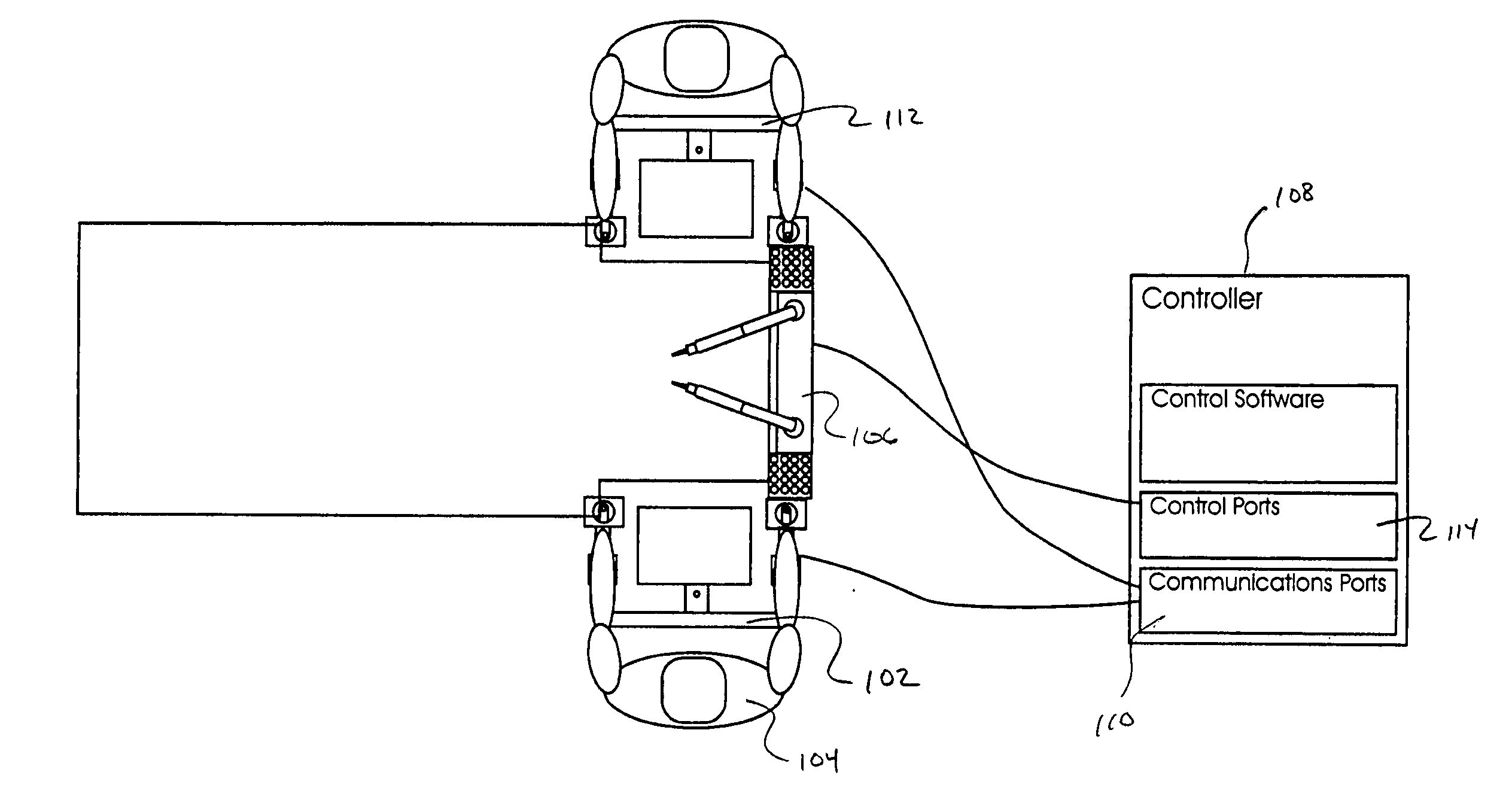
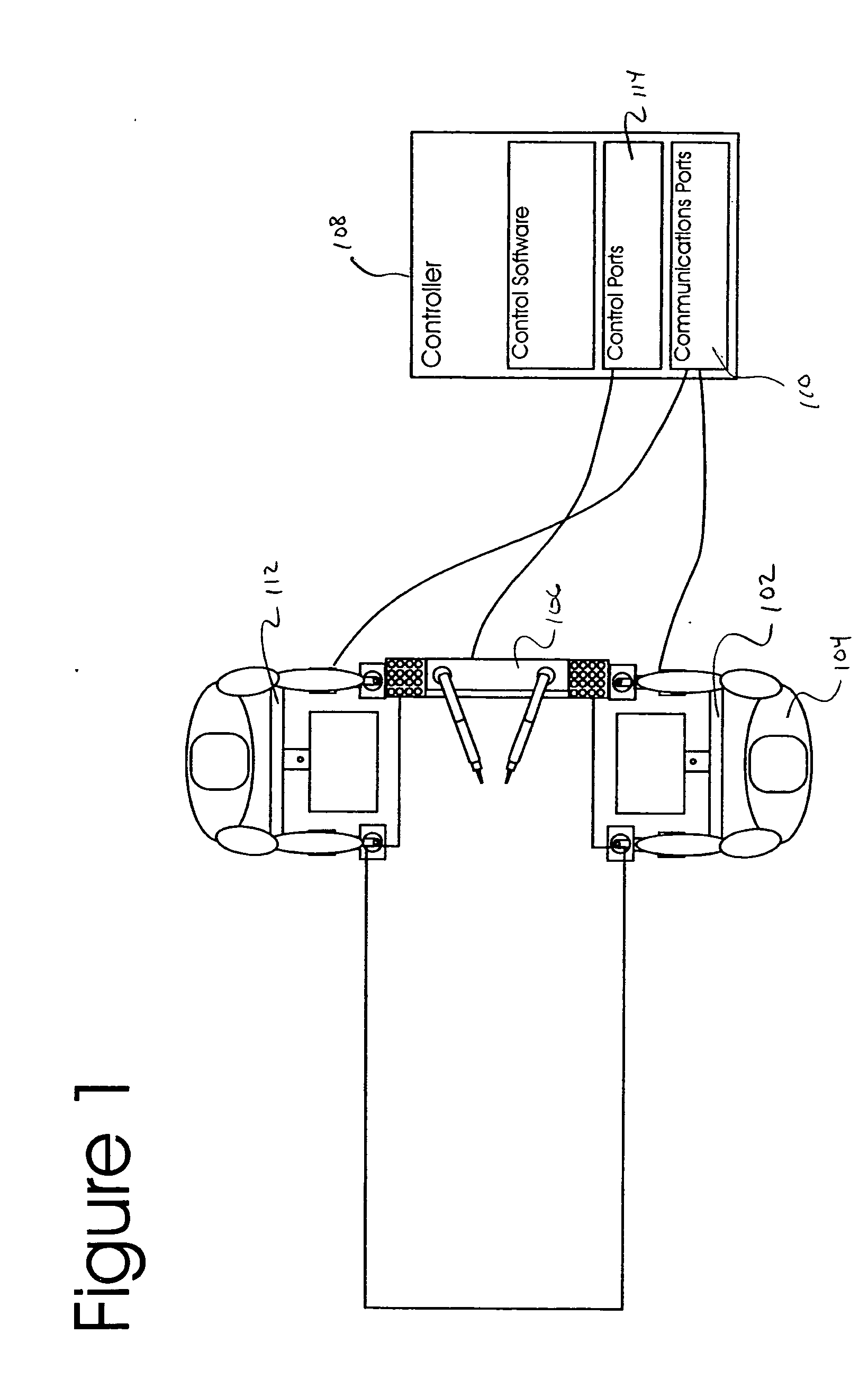
[0022] The present invention relates to an augmented surgical appliance, using an operator interface 102 for a surgeon 104 combined with an augmented surgical unit portion 106 for performing surgical procedures. The interface and surgical unit portions are interconnected via a controller 108, which receives input from the interface 102, and converts the input to output performed by the surgical unit 106. Feedback is provided to the interface 102 from the controller 108 in response to parameters measured at the surgical unit 106.

[0023] As shown in FIG. 1, the controller may be provided with a plurality of communications ports 110 for receiving input from one or more interfaces 102, 112. The controller 108 may also be provided with one or more control ports 114 for providing control signals to the surgical unit 106. As shown in FIG. 1, a single surgical unit 106 may be controlled by a plurality of interface unites 102, 112, where the controller includes functionality for integrating ...


PUM


Abstract

The present invention is a system comprising surgical units and operator interface units configured to provide multiple capabilities within a surgical environment, or within a surgical training environment. The system may provide such capabilities in a modular fashion, such that various functions may be accomplished through the addition or deletion of modules to the system to allow core components to be used to accomplish more than one function.

Description

RELATED APPLICATIONS [0001] This patent application is a non-provisional application and claims priority from U.S. Provisional Patent Application Ser. No. 60 / 617,864, filed Oct. 12, 2004, and from U.S. patent application Ser. No. 10 / 652,722, filed on Dec. 17, 2003, the entire disclosures of which are incorporated by reference herein as if being set forth in their entireties, respectively.FIELD OF THE INVENTION [0002] The present invention relates to the field of robotic and computer assisted surgery, and more specifically to equipment and methods for robotic and computer assisted microsurgery. BACKGROUND [0003] As shown in U.S. Patent 5,943,914 to Morimoto et al., “Master / slave” robots are known in which a surgeon's hand input is converted to a robotic movement. This is particularly useful for motion scaling wherein a larger motion in millimeters or centimeters by the surgeon's input is scaled into a smaller micron movement. Motion scaling has also been applied in cardiac endoscopy,...

Claims


Application Information

Patent Timeline
IPC IPC(8): A61B17/00A61B19/00B31D1/02
CPCA61B1/05A61B19/20A61B19/203A61B19/22A61B19/2203A61B19/52A61B19/5202A61B19/5212A61B19/5223A61B19/5225A61B19/5244A61B19/56A61B2017/00207A61B2017/0046A61B2017/00464A61B2019/2223A61B2019/223A61B2019/2234A61B2019/2249A61B2019/2269A61B2019/2276A61B2019/2288A61B2019/2292A61B2019/2296A61B2019/461A61B2019/464A61B2019/465A61B2019/5229G09B23/28A61B90/10A61B2034/742A61B34/75A61B90/36A61B34/20A61B2090/064A61B34/70A61B90/30A61B34/25A61B90/361A61B34/30A61B90/14A61B34/37A61B34/35A61B2034/305A61B34/72A61B34/74A61B34/76A61B34/77A61B2090/061A61B2090/065A61B90/20A61B90/37A61B2090/372
Inventor LIPOW, KENNETH I.
Owner LIPOW KENNETH I
Why Eureka
Try Eureka