
Frac Pump Isolation Safety System

a safety system and pump technology, applied in the direction of liquid transferring devices, positive displacement liquid engines, borehole/well accessories, etc., can solve the problems of reducing the safety of frac pumps

Inactive Publication Date: 2014-10-02
FTS INT SERVICES
View PDF10 Cites 76 Cited by
  • Summary
  • Abstract
  • Description
  • Claims
  • Application Information

AI Technical Summary

Benefits of technology

The patent describes a system for delivering high-pressure fluids in industrial settings using multiple fluid pumps and a manifold. An isolation valve is used to isolate each pump from the manifold for safety, and a control panel is used to monitor and control the valves and pumps through remote actuation. The system also includes wired and wireless operator interfaces, alternate means of isolation valve actuation, and various system condition monitoring inputs. Another embodiment involves a hydraulic fracturing pump isolation safety system that includes the same components as the industrial system, but adapted for use in hydraulic fracturing operations.

Problems solved by technology

Rock pressures beneath the earth's surface are quite extreme, especially given the depths to which the well holes must be drilled to reach the pay zones.
If these stimulation operations are halted before sufficient amounts of proppant are introduced into the fissures, the fissures can close and negate any progress made to that point.
Because the frac fluid is abrasive and often corrosive, maintenance of frac pumps must occur regularly.
Also, because of the great strains on the frac pumps, breakdowns can occur, hence the need for redundancy.
However, extra precaution must be taken when isolating a frac pump—given the extreme operating pressures involved.
However, with all of the other pumps running, the extreme environment due to the cacophony of noise and the mechanical vibrations of the equipment can make it exceedingly difficult for the operator to determine which valve to operate, or whether the respective frac pump is in a safe condition.
If the wrong valve is closed on an operating frac pump, an essentially instantaneous overpressure and explosion of the valve hardware, lines, and / or fluid head of the pump can occur, possibly leading to equipment destruction, operation and production time losses, operator injury, and attendant costs.

Method used


Image

  • Frac Pump Isolation Safety System
  • Frac Pump Isolation Safety System
  • Frac Pump Isolation Safety System

Examples


Embodiment Construction

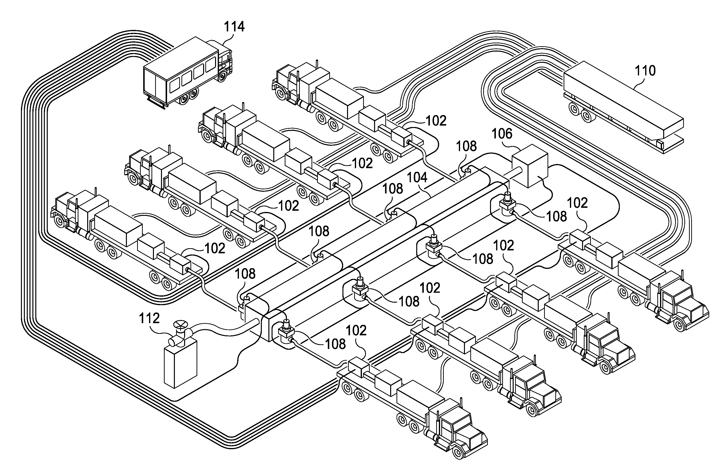
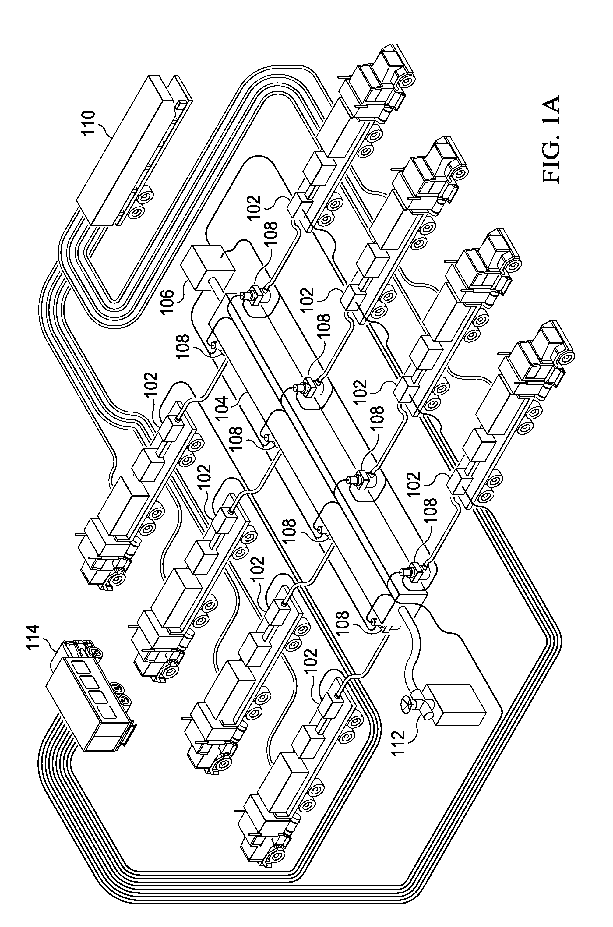
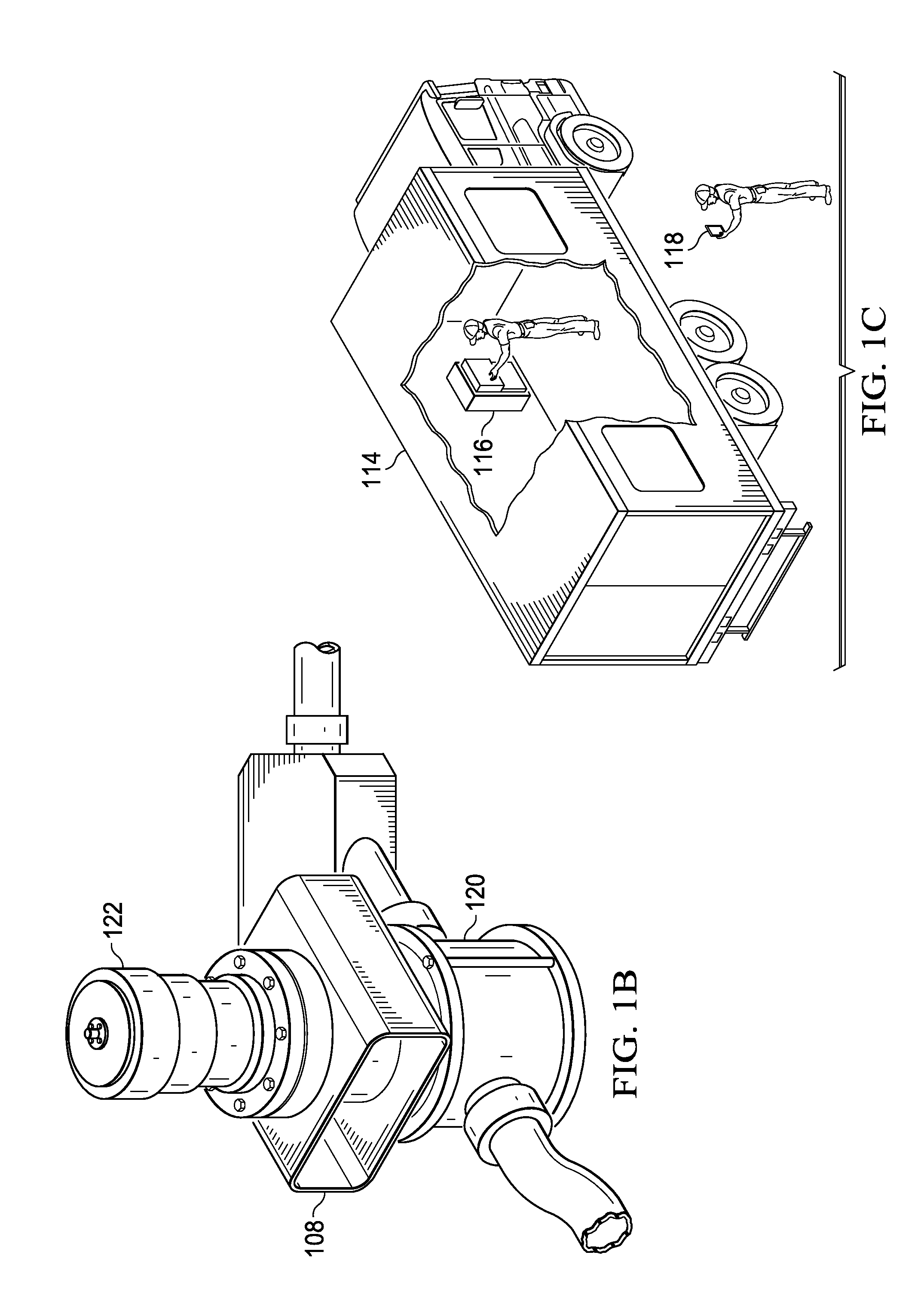
[0025]FIG. 1A depicts a first embodiment of the invention as it applies to a hydraulic fracturing operation during well stimulation, emphasizing the large amount of basic equipment necessary for the fracturing operation. As shown, a plurality of hydraulic fracturing (“frac”) pumps (102) is connected, each in parallel, to a primary fluid manifold (104) to provide frac fluids to a wellhead (112) for well stimulation as previously described. Hydraulically actuated isolation valves (108) provide a means for isolating a frac pump (102) from the manifold (104) to allow for repair or maintenance of the frac pump while avoiding work stoppage. A hydraulic control pump and reservoir (106) provide hydraulic pressure for remote isolation valve (108) actuation. The frac fluids are supplied to each pump (102) from a frac fluid blender reservoir trailer (110). Remote monitoring and control of the equipment occurs from a remote location, for example, a treater truck (114) as depicted.

[0026]FIG. 1B ...


PUM


Abstract

The improved system allows an operator overseeing a well stimulation hydraulic fracturing operation to bring frac pumps online and offline as necessary. A control panel allows the operator to remain at a safe distance from high-pressure equipment, including the frac pumps and respective remotely actuated isolation valves, yet allows monitoring and operation of same. The operating condition of the frac pumps and the isolation valves is monitored by an automated processing device, which prevents operation of same during certain pump and valve conditions. A wireless operator interface is also provided.

Description

CROSS-REFERENCE TO RELATED APPLICATIONS[0001]Not ApplicableSTATEMENT REGARDING FEDERALLY SPONSORED RESEARCH OR DEVELOPMENT[0002]Not ApplicableTHE NAMES OF THE PARTIES TO A JOINT RESEARCH AGREEMENT[0003]Not ApplicableINCORPORATION-BY-REFERENCE OF MATERIAL SUBMITTED ON A COMPACT DISC[0004]Not ApplicableBACKGROUND OF THE INVENTION[0005]1. Field of the Invention[0006]The present invention relates to a system for safe remote monitoring and operation of high-pressure and high-volume industrial fluid delivery system and, more specifically, to a system for remote monitoring and control of hydraulic fracturing equipment in a well stimulation operation.[0007]2. Description of Related Art including information disclosed under 37 CFR 1.97 and 1.98[0008]Horizontal drilling and well stimulation processes have revolutionized the oil and gas industry with regard to the optimization of hydrocarbon extraction. Shale areas once thought unreachable are now within range of the horizontal drilling techno...

Claims


Application Information

Patent Timeline
Patent Type & Authority Applications(United States)
IPC IPC(8): E21B43/26
CPCE21B43/26Y10T137/85986Y10T137/86027E21B43/2607
Inventor RANDLE, COYKREBS, KEVINMEIER, NATHANROBERTSHAW, JUSTINWADE, DON
Owner FTS INT SERVICES
Learn More