
Medical resuscitation system and patient information module

a technology of medical resuscitation system and patient information module, applied in the field of surgery, can solve problems such as inability to perform defibrillation step and some monitoring, lack of communication ability of current aeds, and inability to address them, so as to achieve faster and more effective treatment

Inactive Publication Date: 2006-07-13
HEATH ROGER LEE
View PDF10 Cites 68 Cited by
  • Summary
  • Abstract
  • Description
  • Claims
  • Application Information

AI Technical Summary

Benefits of technology

[0010] The present invention provides a medical resuscitation system having a communication system. The communication system can communicate with an electronic patient information module carried by a patient. The electronic patient information module has medical information corresponding to the patient which it provides to the medical resuscitation system. This information enables the patient to be treated faster and more effectively.
[0011] The treatment is faster because the information is provided to medical personnel assisting the patient. In some examples, the medical personnel can be at a remote location or they can be on the scene. If the medical personnel are at the remote location, the information is sent to them through a communication system. The remote medical personnel can then send a signal to the medical resuscitation system to implement a desired protocol to treat the patient. If the medical personnel on the scene, then the information can be displayed on a display included in the resuscitation system. The treatment is more effective because the medical personnel have the patient's medical information, as provided by the electronic patient information module, and can choose an appropriate protocol based on it.

Problems solved by technology

However, there are several problems not addressed by current AEDs.
Current AEDs, however, can only perform the defibrillation step and some monitoring.
Further, current AEDs are lacking in their ability to communicate information about the patient to a remote location, although there are several monitors which do so.
However, there are several problems that the CardioNet System does not address.

Method used


Image

  • Medical resuscitation system and patient information module
  • Medical resuscitation system and patient information module
  • Medical resuscitation system and patient information module

Examples


Embodiment Construction

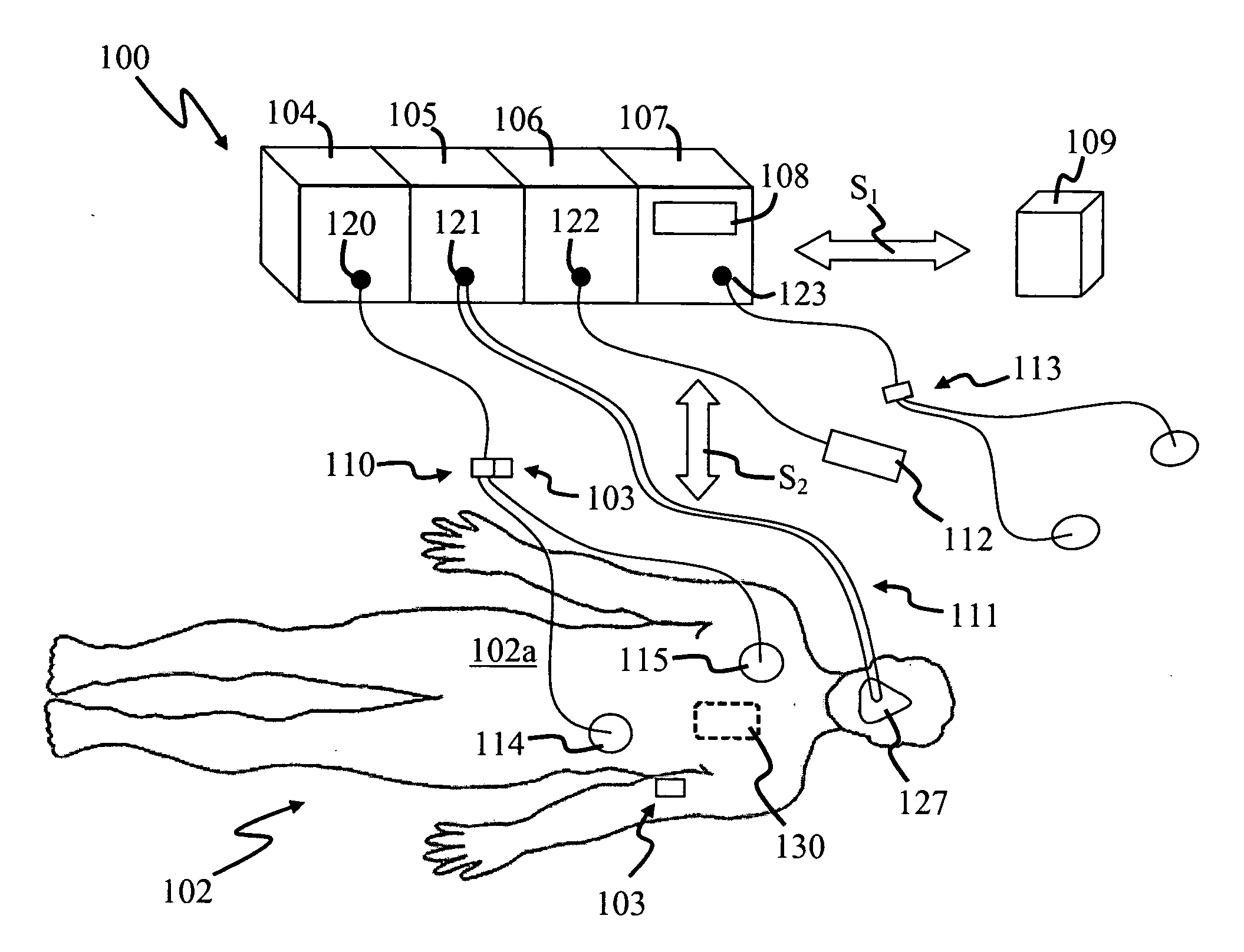
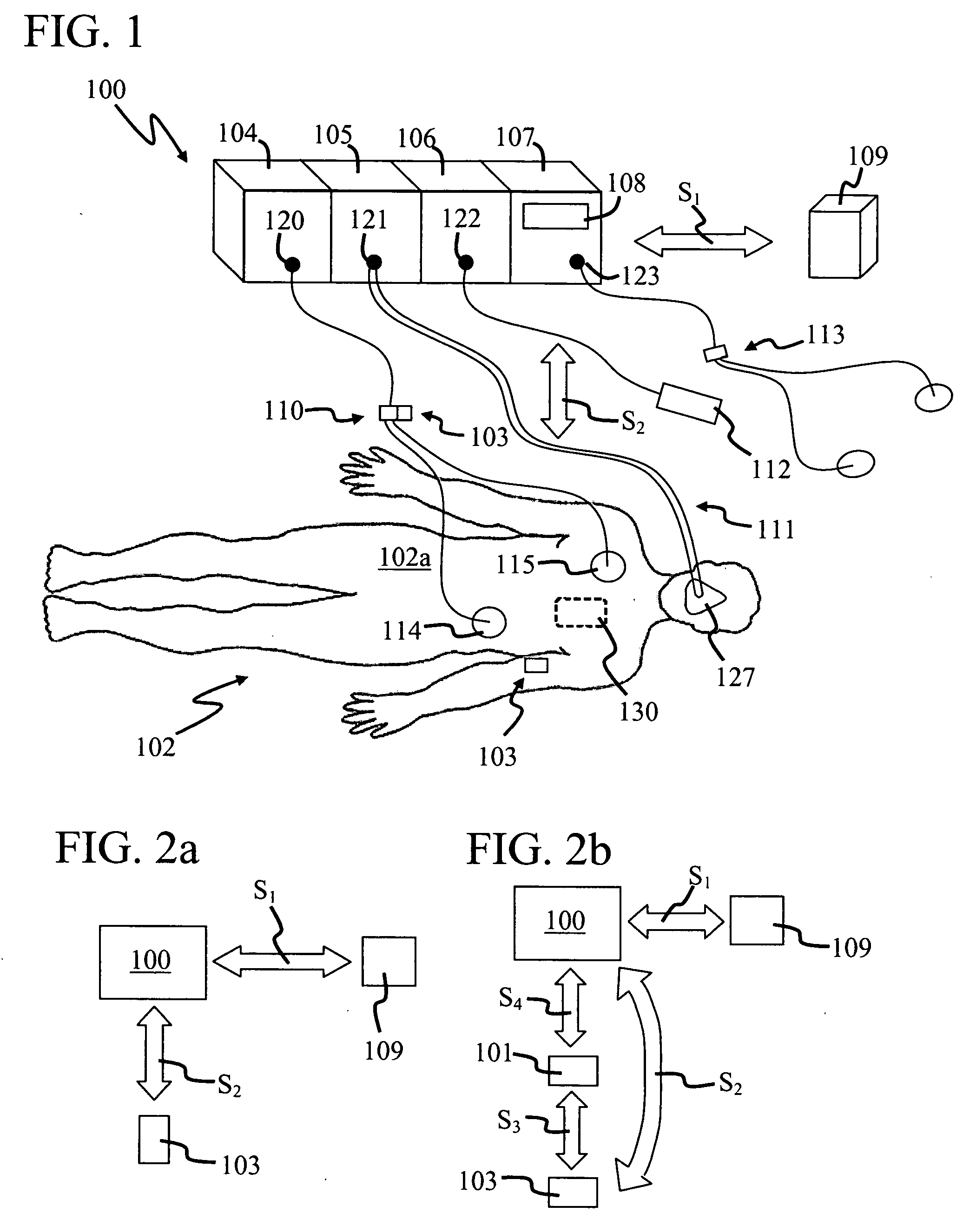
[0023]FIG. 1 is a perspective view of a medical resuscitation system 100, in accordance with the present invention. System 100 provides many different advantages which are discussed in more detail in U.S. patent application Ser. No. 11 / 235,005 (“the '005 application”) filed on Sep. 26, 2005 by the same inventor, and incorporated herein by reference. System 100 can resuscitate a patient 102 because it can ventilate, defibrillate, and / or pace him or her. In this example, system 100 includes a physiological stimulator 104, ventilator 105, communication system 106, and monitor 107. An electrode system 110 is coupled between stimulator 104 at a port 120 and patient 102 to flow a defibrillation and / or pacing signal therebetween. Further, a breathing circuit 111 is coupled between ventilator 105 at a port 121 and patient 102 to provide ventilation thereto. An electrode system 113 is coupled to monitor 107 at a port 123 and is used to monitor the vital signs of patient 102.

[0024] In one em...


PUM


Abstract

A medical resuscitation system includes an external physiological stimulator system module for resuscitating a patient and an external communication system module. The external physiological stimulator and communication system modules are removeably coupled together. The external communication system module can flow a signal between it and an electronic patient information module carried by a patient. The external physiological stimulator system module can resuscitate the patient in response to this signal.

Description

CROSS-REFERENCE TO RELATED APPLICATIONS [0001] This application claims the benefit of U.S. Provisional Application, Ser. No. 60 / 644,122, filed on Jan. 13, 2005.BACKGROUND OF THE INVENTION [0002] 1. Field of the Invention [0003] This invention relates generally to surgery and, more particularly, to a medical resuscitation system which responds to an electronic patient information module. [0004] 2. Description of the Related Art [0005] A number of patients suffer from arrhythmias, such as ventricular fibrillation (VF) and atrial fibrillation (AF), each year and are often referred to as cardiac patients. It is known that the chances of survival increase if the time between the onset of VF and medical treatment decreases. For example, a cardiac patient's chances of survival decrease about 10% for every minute that elapses after VF begins and before defibrillation is initiated. Since most cardiac patients are away from a hospital at the onset of VF, automatic external defibrillators (AED...

Claims


Application Information

Patent Timeline
IPC IPC(8): A61N1/39
CPCA61N1/39G06F19/323A61N1/3904G16H10/65
Inventor HEATH, ROGER LEE
Owner HEATH ROGER LEE
Learn More