Patient-specific cutting guide for the shoulder

a cutting guide and shoulder technology, applied in the direction of bone drill guide, surgery, diagnostics, etc., can solve the problems of decreased mobility, pain, stiffness, bone and joint damage, etc., to achieve high degree of accuracy, accurate and quick shoulder arthroplasty procedure, and restore the natural alignment of the join

Active Publication Date: 2014-06-26
HOWMEDICA OSTEONICS CORP
View PDF4 Cites 28 Cited by
  • Summary
  • Abstract
  • Description
  • Claims
  • Application Information

AI Technical Summary

Benefits of technology

[0009]Patient-specific cutting guides for resecting the humerus and glenoid in a preoperatively planned manner are described herein. These patient-specific guides are configured to allow a surgeon to accurately and quickly perform a shoulder arthroplasty procedure that substantially restores the natural alignment of the joint. Specifically, the patient-specific guides are shaped such that they matingly receive the regions of the bone to be subjected to a treatment (e.g., cutting, drilling, reaming, and / or resurfacing). The patient-specific guides are also shaped to provide the proper location and orientation of the treatment relative to the regions of the bone. The shaped aspect of the patient-specific guides allows the treatment of the bone regions to be done quickly and with a high degree of accuracy that will allow the implants to restore the patient's joint to a generally pre-deteriorated state.

Problems solved by technology

Over time and through repeated use, bones and joints can become damaged or worn.
When the cartilage wears down, fluid can accumulate in the joint areas, resulting in pain, stiffness, and decreased mobility.
The same can happen in the case where tendons in a joint become lax or soft tissues in or adjacent the joint tear become damaged or worn.
A one to two millimeter translational misalignment, or a one to two degree rotational misalignment, may result in imbalanced ligaments, and may thereby significantly affect the outcome of the procedure.
For example, implant misalignment may result in intolerable post-surgery pain, and also may prevent the patient from having proper deltoid tension or range of motion.
Currently available instrument and tools do not always enable the surgeon to make the most accurate cuts on the bone surface in preparing the target joint for implantation.

Method used


Image

  • Patient-specific cutting guide for the shoulder
  • Patient-specific cutting guide for the shoulder
  • Patient-specific cutting guide for the shoulder

Examples


Embodiment Construction

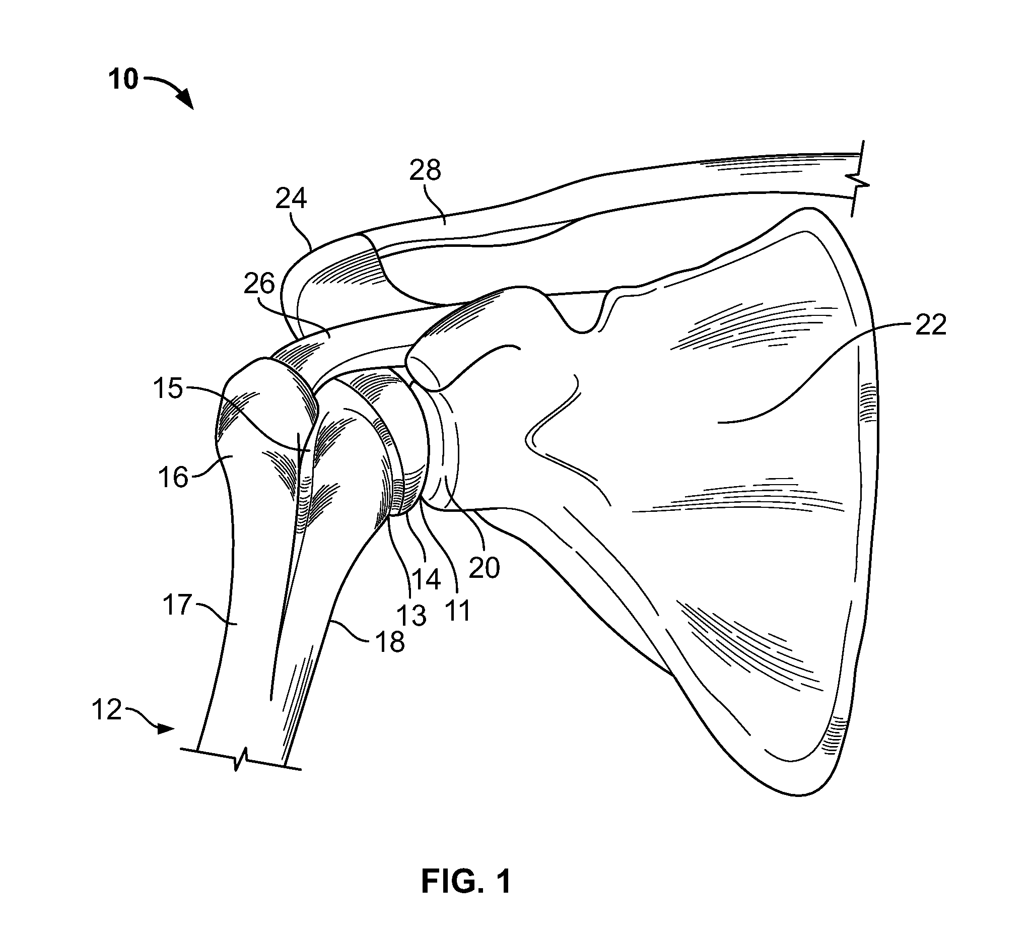
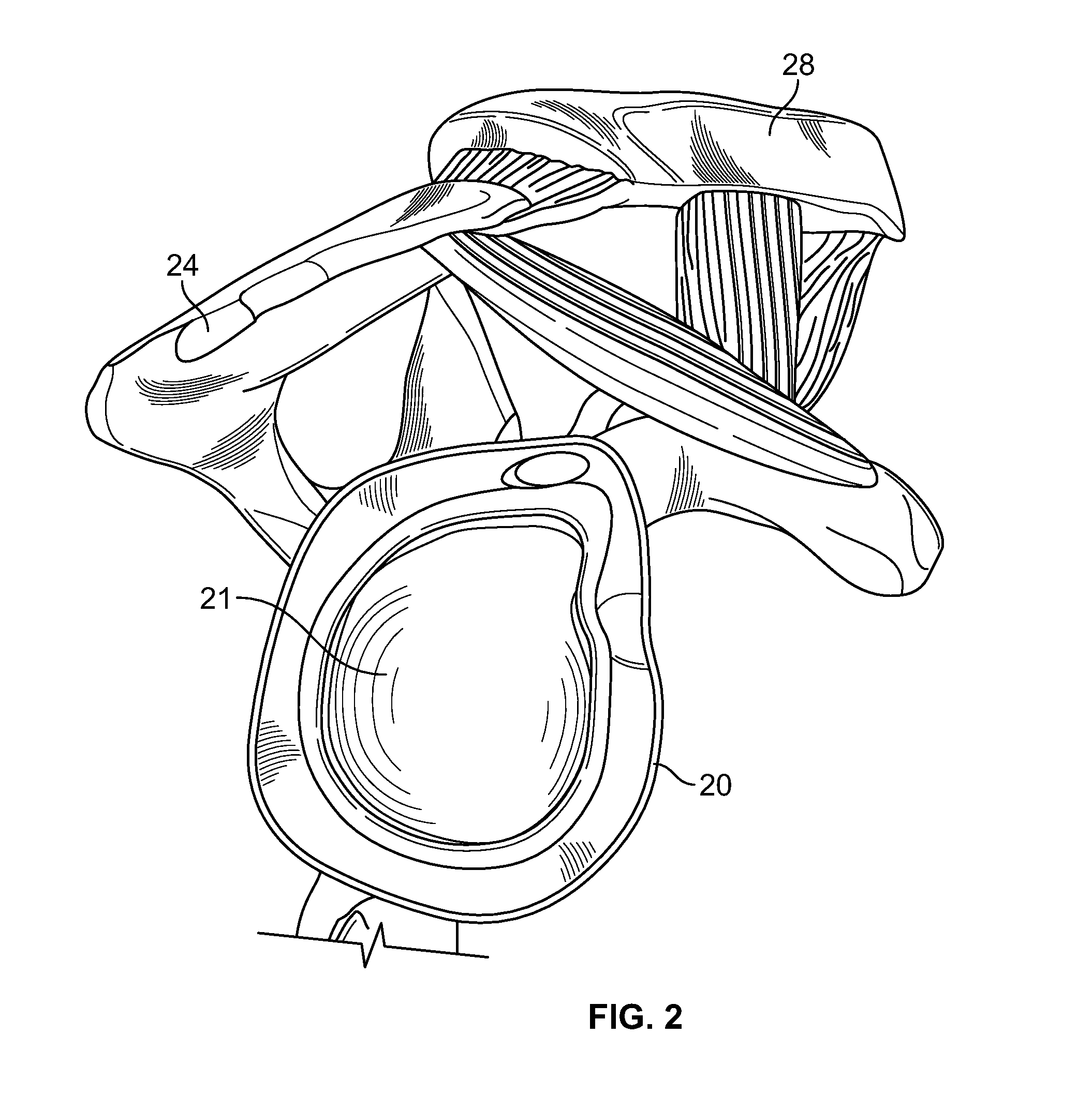
[0020]FIG. 1 shows the general anatomy of shoulder joint of a patient. Humerus 12 of joint 10 includes a neck portion 13, a head portion 14 and a shaft portion 17 having a greater tuberosity 16 and a lesser tuberosity 18. Between greater and lesser tuberosities 16, 18 is bicipital groove 15. As shown in FIGS. 1-2, scapula 22 terminates at glenoid 20 having a cavity 21 in which an outer surface 11 of head portion 14 rotates within. Along with humerus 12 and scapula 22, the acromion 24, rotator cuff 26 and clavicle 28 all provide support to the range of motion of the shoulder joint 10 of the patient.

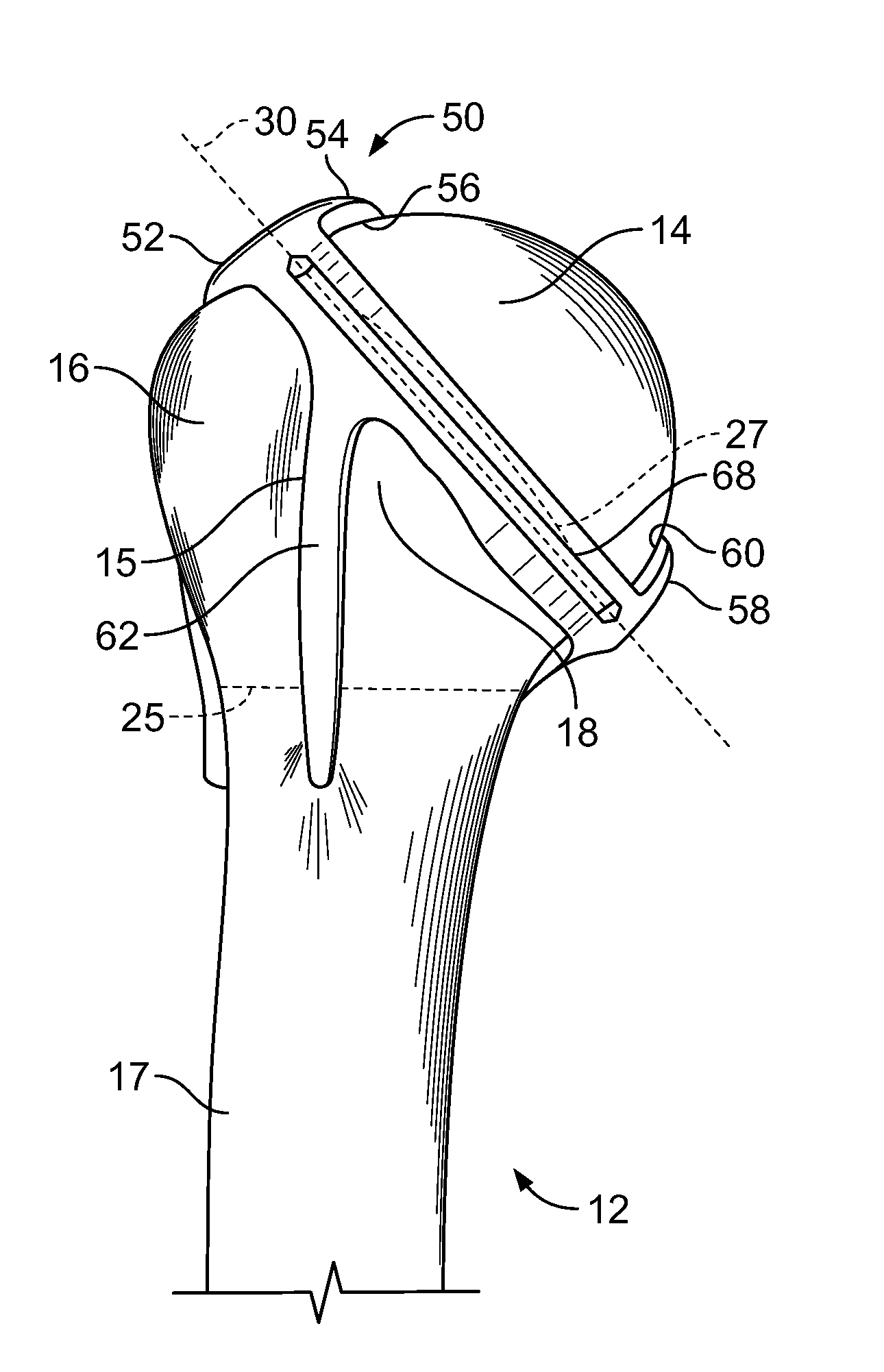
[0021]FIG. 3 is a posterior view of a proximal portion of humerus 12 of shoulder joint 10. Head portion 14 includes outer surface 11. Also shown is bicipital groove 15, a substantially straight surcical neck line 25 and a curvy anatomical neck line 27. Outer surface 11, biciptal groove 15, substantially straight surcical neck line 25 and curvy anatomical neck line 27 are all anatomical fea...


PUM

PropertyMeasurementUnit
diameteraaaaaaaaaa
angleaaaaaaaaaa
shaft angleaaaaaaaaaa

Abstract

Disclosed herein are devices and methods for guiding a surgical instrument for resecting a portion of a humerus of a patient. The surgical instrument is a patient-specific cutting guide having a base portion having a contact surface shaped to substantially match an outer surface of a neck portion of the humerus. The guide includes at least one proximal stabilization member extending medially from the base portion and having a contact surface shaped to substantially match an outer surface of a head portion of the humerus. The guide further includes at least one distal stabilization member extending distally from the base portion and having a contact surface shaped to substantially match an outer surface of a shaft portion of the humerus. The base portion includes a guide slot for guiding the surgical instrument.

Description

CROSS-REFERENCE TO RELATED APPLICATION[0001]The present application claims the benefit of the filing date of U.S. Provisional Application No. 61 / 494,579, filed Jun. 8, 2011, entitled, “Patient-Specific Cutting Guide For The Shoulder,” the disclosure of which is hereby incorporated herein by reference.FIELD OF THE INVENTION[0002]The present invention relates to patient-specific cutting guides for the shoulder, and in particular it relates to such cutting guides having a patient-specific contact surface shaped to rest on bone in a predetermined manner, the guides having at least one guide hole or slot used to resect bone as preoperatively planned such that a corresponding implant can be located and oriented on the resected bone in a predefined manner.BACKGROUND OF THE INVENTION[0003]Over time and through repeated use, bones and joints can become damaged or worn. For example, repetitive strain on bones and joints (e.g., through athletic activity), traumatic events, and certain diseases...

Claims


Application Information

Patent Timeline
Patent Type & Authority Applications(United States)
IPC IPC(8): A61B17/17
CPCA61B17/1739A61B17/15A61B2034/108A61B17/1778G16H50/50Y10T29/49A61B17/1684A61B2090/033
Inventor BUZA, LUKEBARILE, GENNARO A.
Owner HOWMEDICA OSTEONICS CORP
Why Eureka
Try Eureka