Vacuum cleaner with collapsible handle

Inactive Publication Date: 2006-07-20
ELECTROLUX HOME CARE PRODS
View PDF98 Cites 114 Cited by
  • Summary
  • Abstract
  • Description
  • Claims
  • Application Information

AI Technical Summary

Problems solved by technology

However, such vacuums often share the stick vacuum objective of being smaller or more compact than typical uprights and canisters.

Method used


Image

  • Vacuum cleaner with collapsible handle
  • Vacuum cleaner with collapsible handle
  • Vacuum cleaner with collapsible handle

Examples


Embodiment Construction

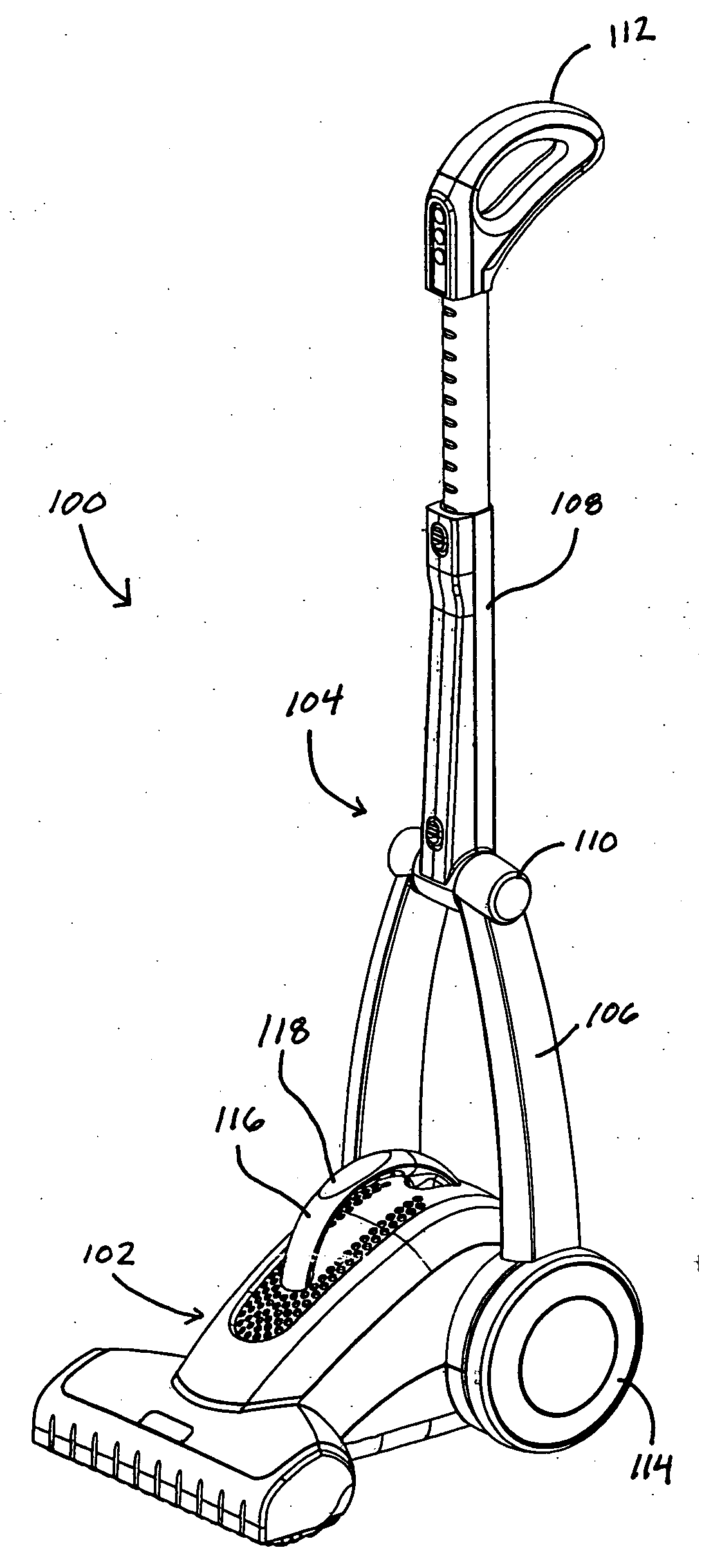
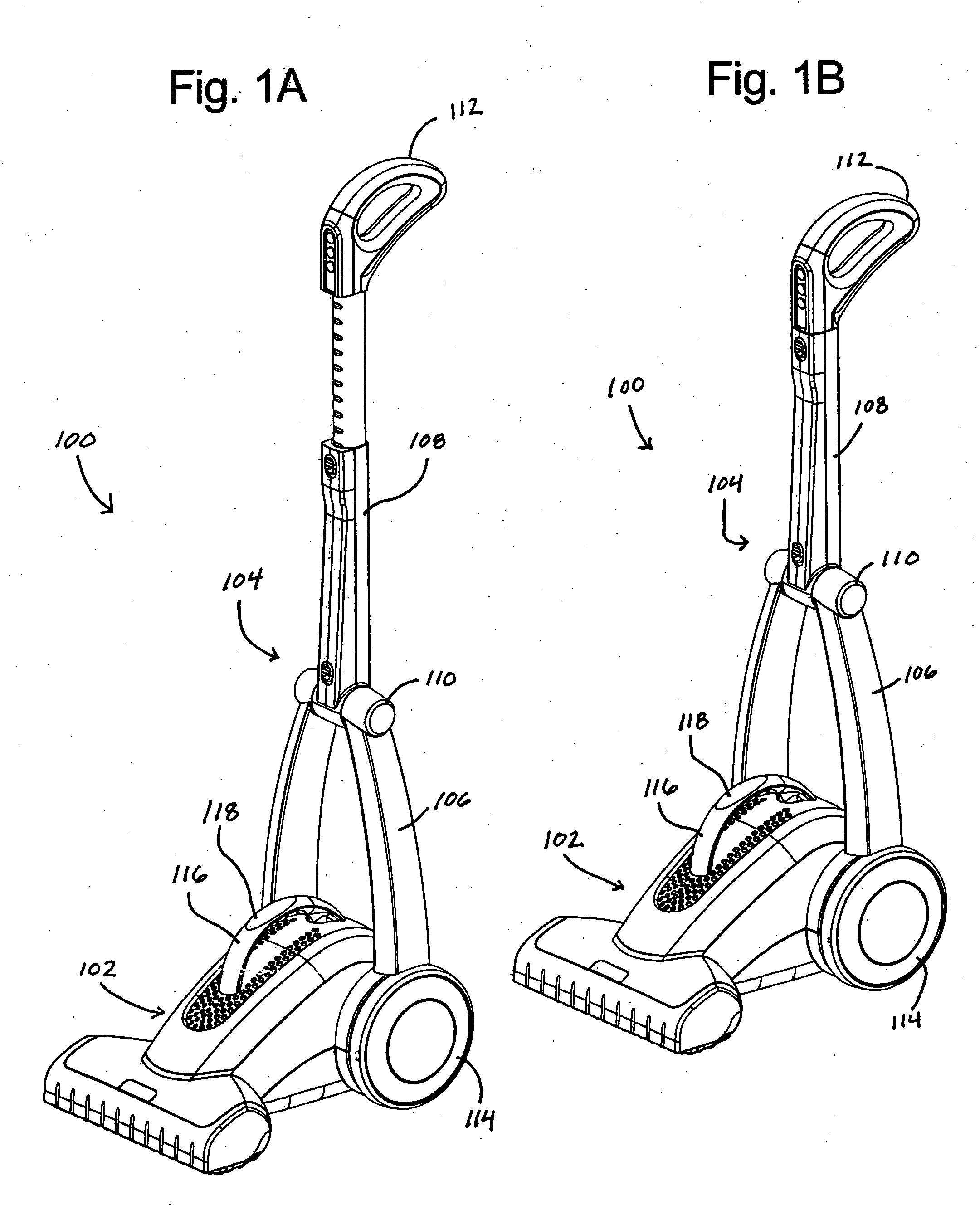
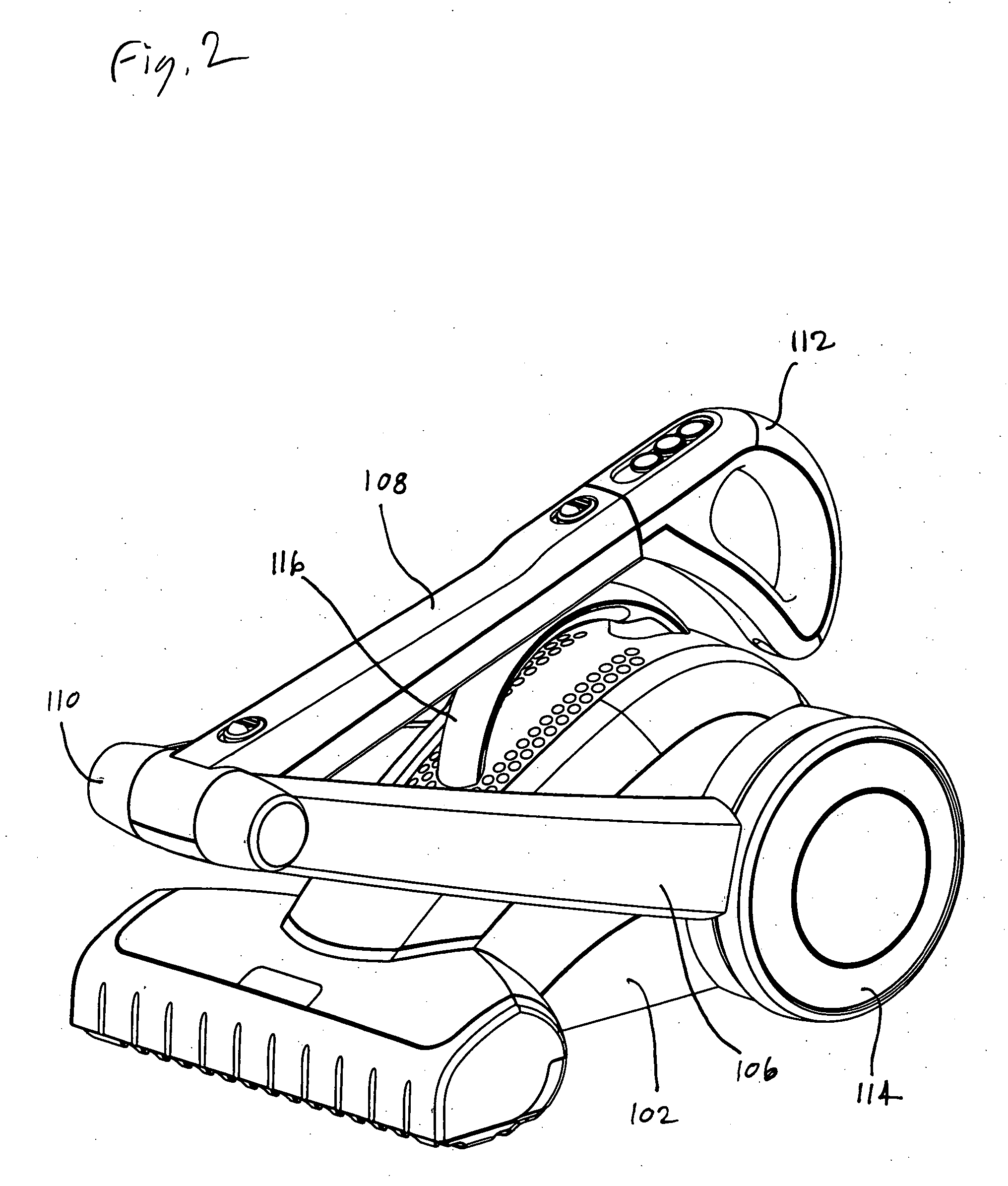
[0031] The present invention generally provides a unique vacuum cleaner having a collapsible handle. While the embodiments described herein and illustrated in the accompanying figures are depicted as a vacuum cleaner, it will be understood that the invention can also be practiced as a wet or dry extractor, or as other types of special-purpose vacuum cleaners. As used herein, the expressions “vacuum cleaner” and “vacuum” are intended to include any cleaning device that uses a suction source to remove dirt or other undesirable substances from surfaces, regardless of whether it includes specialty features, such as a fluid deposition system and fluid recovery tank (as in wet extractors), and regardless of what type of dirt separation system it uses (such as cyclonic, bag, or dirt cup separation systems). These and other variations will be apparent to those of ordinary skill in the art in view of the present disclosure.

[0032] Referring now to FIGS. 1A, 1B and 2, an embodiment of the inv...


PUM


Abstract

A vacuum cleaner having a base adapted to be moved on a surface to be cleaned, an inlet nozzle disposed on a lower surface of the base, a vacuum source, and a dirt receptacle. A lower handle is pivotally attached to the base at a lower pivot, and an upper handle is pivotally attached to the lower handle at an upper pivot. In one aspect, the vacuum cleaner includes an automatically-operated lower pivot lock that can restrict relative rotation between the lower handle and the base, and a manually-operated upper pivot lock that can restrict relative rotation between the upper handle and the lower handle. In another aspect, the vacuum cleaner includes a telescoping upper handle with electrical controls attached to the upper telescopic section of the upper handle. In still another aspect, the vacuum cleaner includes an exhaust vent located on an upwardly-facing surface of the base.

Description

CLAIM OF PRIORITY [0001] This patent claims priority to U.S. Provisional Application Nos. 60 / 644,020, filed on Jan. 18, 2005, and 60 / 673,359, filed on Apr. 21, 2005, each of which is incorporated herein by reference in its entirety.FIELD OF THE INVENTION [0002] The present invention relates generally to floor cleaning devices having collapsible handles. BACKGROUND OF THE INVENTION [0003] Electric vacuum cleaners are in widespread use in homes, offices and other places where quick and efficient floor cleaning is desired. Such vacuum cleaners are provided in various configurations, such as upright, canister, “stick,” and “powerhead” designs. [0004] Upright vacuums are typically provided having a relatively large floor-engaging, wheeled nozzle base to which a pivoting rear housing / handle is attached. The base includes a suction nozzle directed towards the floor, and the rear housing includes a dirt storage receptacle (such as a cyclonic or non-cyclonic dirt separation chamber or a vacu...

Claims


Application Information

Patent Timeline
Patent Type & Authority Applications(United States)
IPC IPC(8): A47L9/32
CPCA47L5/30A47L9/0009A47L9/1472A47L9/2821A47L9/2842A47L9/2857A47L9/2878A47L9/2889A47L9/325A47L9/32
Inventor LUEBBERING, GREGORY W.HAMPTON, LEONARDBOBROSKY, VINCENTSEPKE, ARNOLDSMITH, JEFFREYBLOOM, SCOTT
Owner ELECTROLUX HOME CARE PRODS
Why Eureka
Try Eureka