
Single cup pod beverage brewer

a single-cup pod and beverage brewing technology, applied in beverage vessels, household appliances, kitchen equipment, etc., can solve problems such as limited devices, and achieve the effect of optimizing power consumption and simple operation

Inactive Publication Date: 2007-05-01
ROLFES PATRICK J +1
View PDF11 Cites 111 Cited by
  • Summary
  • Abstract
  • Description
  • Claims
  • Application Information

AI Technical Summary

Benefits of technology

[0012]Since the use of a pod is now becoming popular in this country, it is a primary object of the invention to have a device for commercial use that brews not only coffee one cup at a time but also tea and further includes hot water for hot chocolate or soup etc. This invention fills the need in commercial areas such as businesses offices and factories etc. where the brewing of a large pot or carafe is impractical. Further the instant brewing of the beverage permits a fresh cup rather than trying to keep the brew hot over a period of time without deterioration of taste and aroma. It may be clearly seen that the invention fills the need easily for a large segment of the population.
[0017]Yet another object of the invention that an electronic controller printed circuit board contains a complete series of trouble shooting LEDs which indicate the function of the system. This feature makes it extremely easy for maintenance personnel to locate any problems in the controls.
[0018]A further object of the invention is that solid state D.C. controls including solenoids and gear motors are utilized in conjunction with A. C. hot water heating system which optimizes power consumption and simplicity of operation.

Problems solved by technology

Automatic beverage brewers, particularly for commercial establishments, have been commonly used for some time however these devices have been limited to relatively large quantities of beverage to be supplied.

Method used


Image

  • Single cup pod beverage brewer
  • Single cup pod beverage brewer
  • Single cup pod beverage brewer

Examples


Embodiment Construction

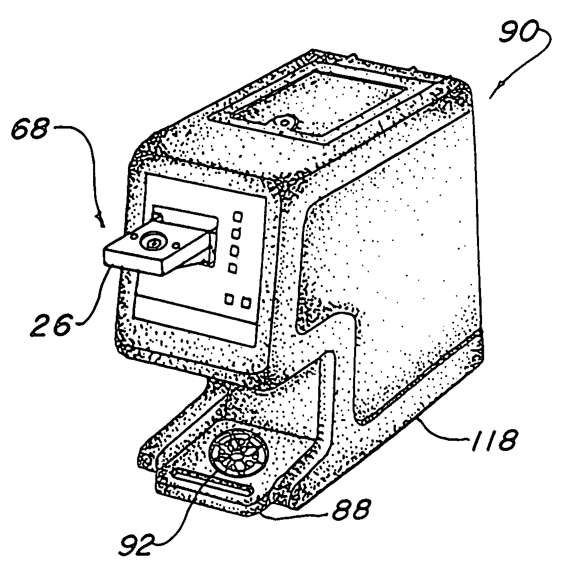
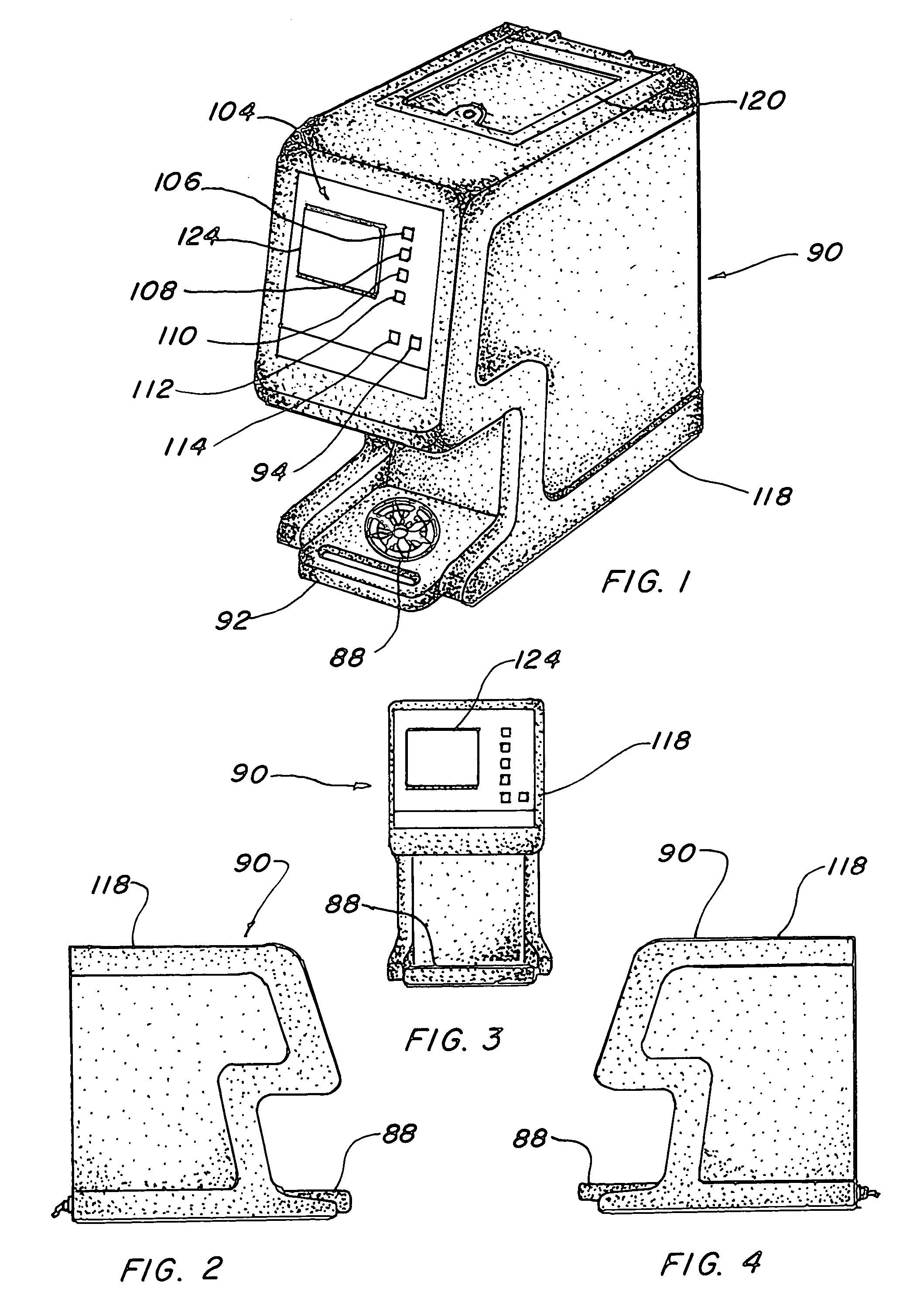
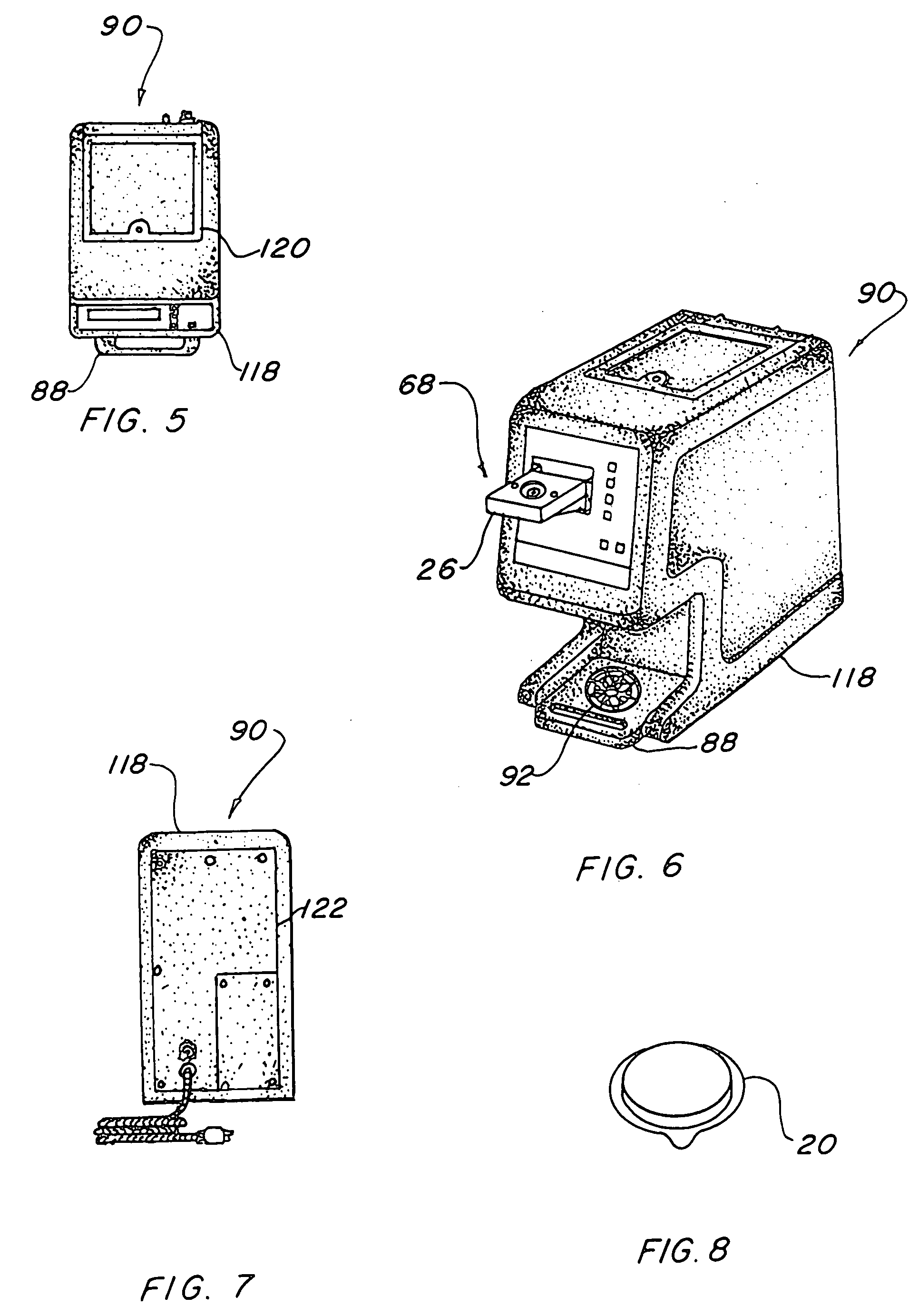
[0058]The best mode for carrying out the invention is presented in terms of a preferred embodiment. This preferred embodiment of a single cup pod beverage brewer is shown in FIGS. 1 thorough 37 and utilizes a pod 20 containing coffee grounds or tea leaves surrounded by filter paper formed in a disc-like shape. FIG. 8 illustrates this pod which is recently becoming popular in this country. It should be recognized that the same shape and size of pod 20 is used for both coffee and tea beverages therefore the same mechanism may be utilized for handling and processing the pod 20 in the invention.

[0059]A pod holding chamber 22 is employed to retain the pod 20 and includes a recess 24 therein configured to mate with the pod 20 without crushing it and yet securely gripping the filter paper on its periphery. The holding chamber 22 is formed in two separate halves which comprise an upper head 26 and a lower head 28 with the upper head 26 having a hot water inlet 30 and the lower head 28 havin...


PUM


Abstract

A single cup pod beverage brewer is presented utilizing a pod (20) containing coffee grounds or tea leaves surrounded by filter paper. A pod holding chamber (22) consisting of a upper head (26) and a lower head (28) having an ejection disc (42). An upper head mounting frame (48) is attached to its horizontal base (50) and includes lower head rotating arms (60) attached to a first shaft (62) with a first gear motor (66) rotating the arms into a pod loading position, a pod brewing position and a pod disposal position. A second gear motor (66a) is secured to the upper head mounting frame, driving a cam (76) through a second shaft (62a) engaging the upper head to lower, seal and raise said upper head. A pod ejector solenoid (84) is disposed on the base electromechanically propelling the pod from the chamber when the lower head in the pod disposal position. An electronic control system employs a solid state direct current arrangement for control regulation and alternating current for heating system functions. An enclosure with panels and a door (90) protects moving elements and electrical controls.

Description

TECHNICAL FIELD[0001]The present invention relates to beverage brewers in general. More specifically to a single cup brewer utilizing a pod for automatically brewing coffee or tea one cup at a time with a pod that contains coffee grounds or tea leaves surrounded by filter paper formed into a disc-like shape.BACKGROUND ART[0002]Previously, many coffee and tea brewing apparatus have been used in endeavoring to provide an effective means to automatically brew beverages, however in most cases the effort has been directed to loose grounds or leaves in large batches for multiple cups brewing.[0003]The prior art listed below did not disclose patents that possess any of the novelty of the instant invention; however the following U.S. patents are considered related:[0004]U.S. Pat. No.InventorIssue Date5,875,703RolfesMar. 2, 19995,836,236Rolfes et al.Nov. 17, 19985,404,794Patel et al.Apr. 11, 19955,161,455Anson et al.Nov. 10, 19925,063,836PatelNov. 12, 19914,791,859KingDec. 20, 1988[0005]Rolf...

Claims


Application Information

Patent Timeline
IPC IPC(8): A47J31/06A47J31/40
CPCA47J31/368
Inventor ROLFES, PATRICK J.ROLFES, PAUL E.
Owner ROLFES PATRICK J
Learn More