RF antenna integrated into a control device installed into a wall switch box

a technology of rf antenna and control device, which is applied in the direction of thermoelectric devices, tumbler/rocker switches, instruments, etc., can solve the problems of unbalanced transmission lines, excitation currents on the ground, and unbalanced transmission lines ideally carrying differential mode currents

Active Publication Date: 2010-07-13
LEVITON MFG
View PDF89 Cites 111 Cited by
  • Summary
  • Abstract
  • Description
  • Claims
  • Application Information

AI Technical Summary

Benefits of technology

[0016]One advantage of the invention is that the strap can extend outside of the housing. The strap is in the form of a plate which can be made from aluminum. Coupled to the strap is at least one antenna coupler. This antenna coupler is comprised of a dielectric material which effectively isolates the antenna from the strap. This antenna coupler includes a channel for receiving the antenna and at least one prong for selectively securing the antenna to the support plate.
[0017]In one example embodiment, the antenna can comprise a flexible wire that can be any shape such as in an L shape and disposed inside a thin insulation, and mounted on the strap plate so as to be concealed by the cover plate of the wall switch. The antenna is “tuned” with respect to the ground plane of the printed circuit board of the lighting control, and the metal surrounding the antenna. The antenna is capacitively coupled to the circuit board of the lighting control so as to prevent any electrical hazard with respect to the line voltage supplied to the control circuit. The compact antenna design provides flexibility with regard to changing the color of the frame or wall plate. In addition, because of the presence of the antenna feed point, the antenna is also not disturbed by any hand or body effect located in close proximity to the switch so that there is no detuning of the circuit due to any hand or body effect.

Problems solved by technology

In most cases, the connection between RF circuits consists of an unbalanced transmission line, such as for example a coaxial cable, or a microstrip transmission line.
Unbalanced transmission lines ideally carry differential mode currents only.
However because an antenna inherently interacts with the environment, it can excite currents on the ground if not interfaced properly.
This can lead to common mode currents.
Common mode currents result in that an unintended voltage is established somewhere besides the antenna.
One effect is that the performance can be sacrificed because power can be lost as the voltage induced radio waves are radiated inside of the appliance.
Alternatively, destructive interference is established resulting in a highly irregular radiation pattern.
However, this antenna is not mounted on the circuit board but capacitively coupled to the printed circuit board.

Method used


Image

  • RF antenna integrated into a control device installed into a wall switch box
  • RF antenna integrated into a control device installed into a wall switch box
  • RF antenna integrated into a control device installed into a wall switch box

Examples


Embodiment Construction

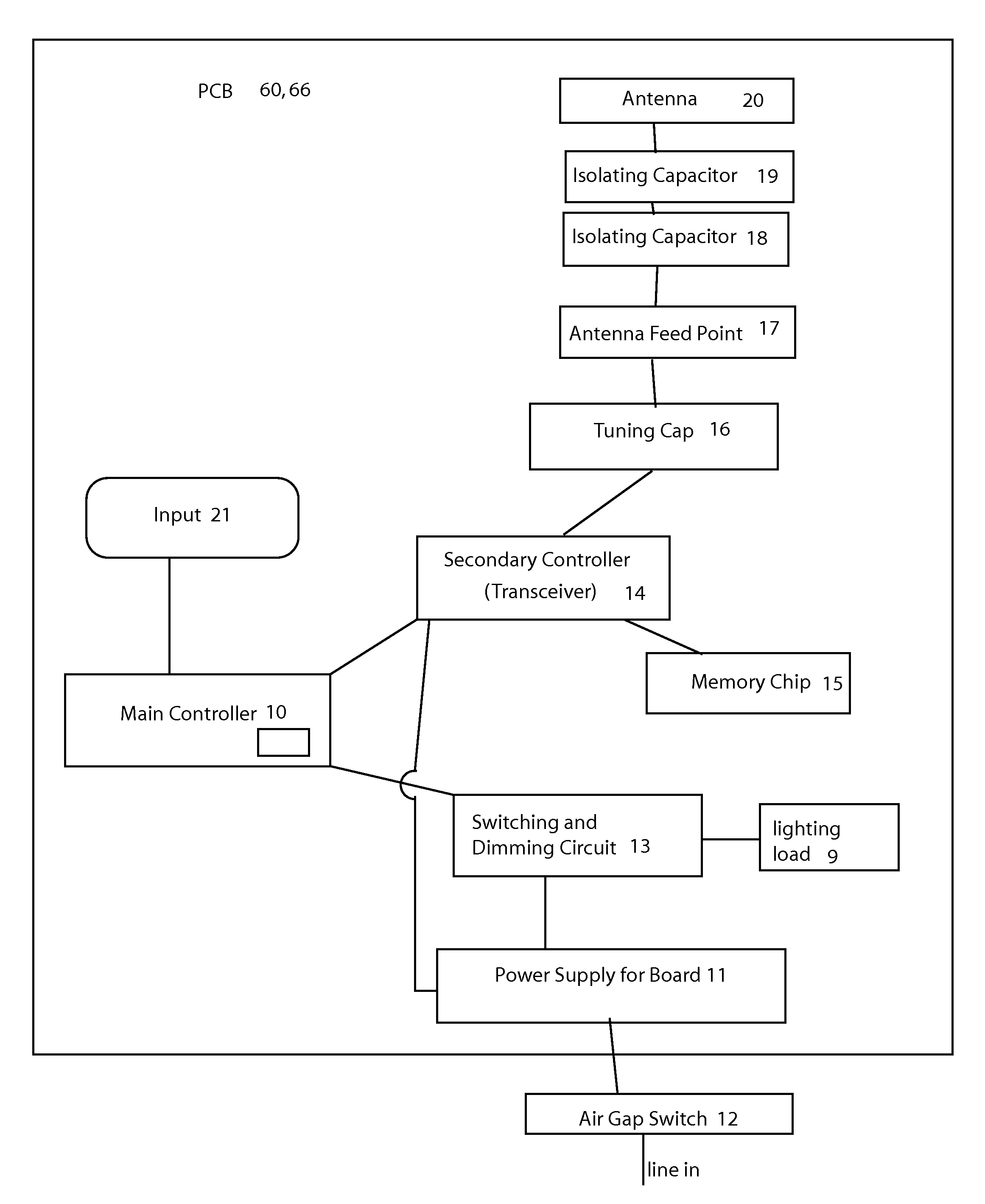
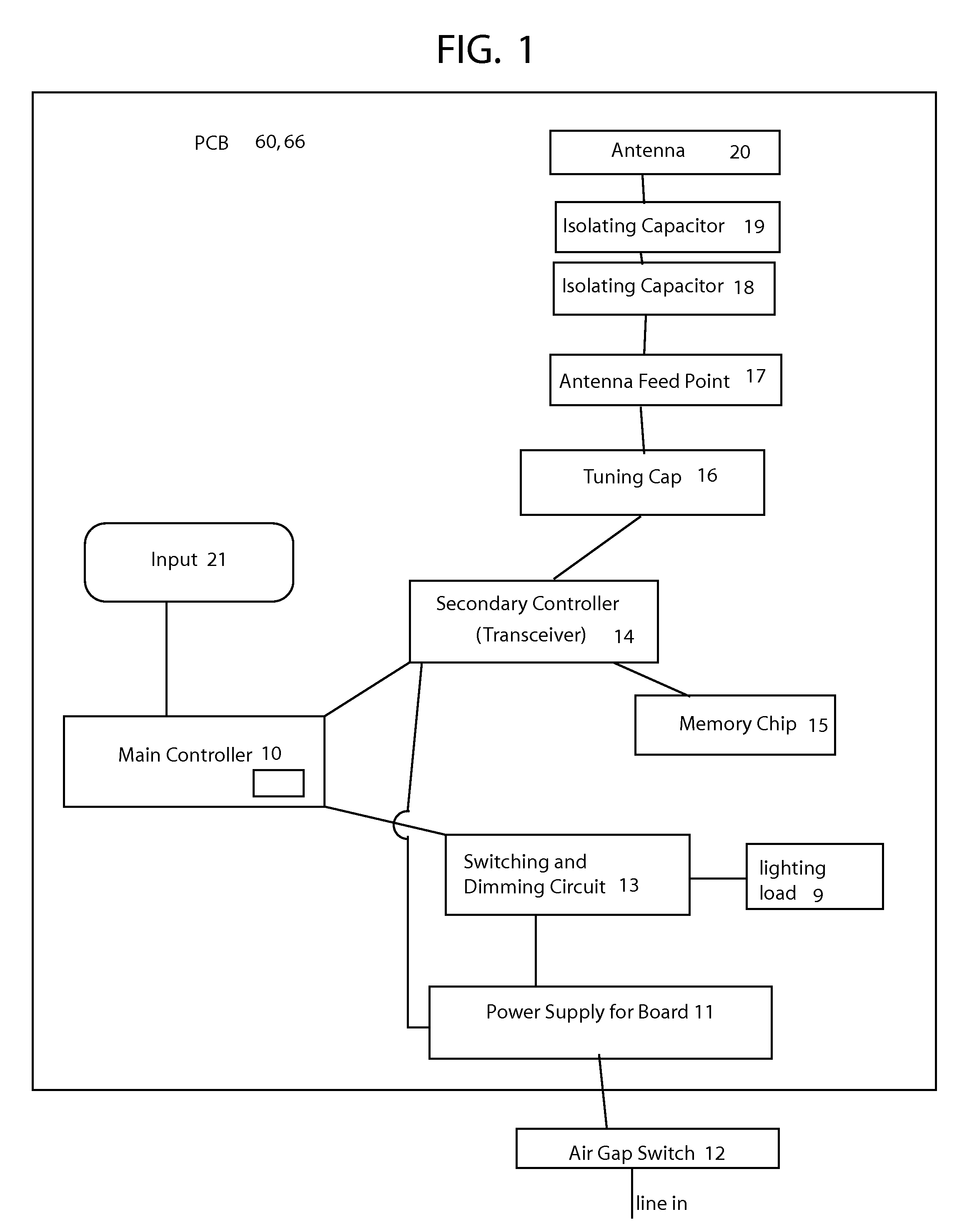
[0039]Referring to FIG. 1, there is shown a block diagram of a preferred embodiment of the present invention showing a main power controller 10, and a power supply 11, which in turn is coupled through an air gap switch 12 to a main power source such as 110 volts AC. Main controller 10 may be any switching control circuit capable of handling the lighting load which is connected to it. The output of main controller 10 connects to a switching and dimming circuit 13, and to a secondary controller or transceiver 14. The antenna circuit comprises a tuning capacitor 16 coupled to an antenna feed point 17, which in a preferred embodiment is coupled to isolating capacitors 18 and 19, however, an antenna circuit in accordance with this invention may be include less than, or more than 2 isolating capacitors. These isolating capacitors are in turn connected to the actual antenna line 20.

[0040]Air gap switch 12, which is connected to the 110 volt AC line, is a mechanical switch or relay that wil...


PUM


Abstract

A remote control electrical device which can communicate with a remote control device. The electrical control device is adapted to fit into a housing which fits into a wall mounting. The remote control electrical device can comprise a control circuit disposed in the housing, a transmitter disposed in the housing, a receiver disposed in the housing wherein said transmitter and said receiver are in communication with the control circuit. There is also a support plate having an inside face facing into the housing and an outside face facing away from the housing body. The support plate is coupled to the housing, wherein there is also an antenna disposed on the outside face of the support plate. This antenna does not receive any power-line AC frequencies or DC, instead it is capacitively coupled to the rest of the electrical components and disposed on the outside face of the support plate.

Description

BACKGROUND OF THE INVENTION[0001]The invention relates to a device for integrating a compact RF antenna held for transmitting and receiving radio frequency signals, into a wireless lighting control system installed in a standard electrical wall box. Other antennas may generally relate to this field. For example, the following U.S. patents generally relate to the field: U.S. Pat. No. 4,138,684 to Kerr; U.S. Pat. No. 4,939,702 to Urbish et al; U.S. Pat. No. 5,079,559 to Umetsu et al; U.S. Pat. No. 5,400,041 to Strickland; U.S. Pat. No. 5,982,103 to Mosebrook et al, wherein the disclosures of all of these patents are hereby incorporated herein by reference.[0002]A good or effective antenna can create an electromagnetic (EM) field in space. This antenna will have a radiation resistance that is much larger than the loss resistance. In that way, radio frequency (RF) power is dissipated into space as opposed to dissipated in the antenna materials.[0003]In addition, an effective antenna pre...

Claims


Application Information

Patent Timeline
Patent Type & Authority Patents(United States)
IPC IPC(8): H04M1/00
CPCH01H23/025H01H23/16H01H2221/044H01H2219/062H01H2001/5888
Inventor PATEL, PARIMALGUTHRIE, WARRENESTANISLAO, DANILO
Owner LEVITON MFG
Why Eureka
Try Eureka