Rack system, adapter, rack frame, support rail, and method of making a rack system

a technology of support rails and racks, applied in the direction of dismountable cabinets, furniture parts, movable shelf cabinets, etc., can solve the problems of inability to attach support rails of one kind of rack frame to different kinds of rack frame, undesirable in terms of control (e.g. management), cost, etc., and achieve the effect of increasing the versatility of the support rail and lowering the cost of the rack

Inactive Publication Date: 2006-07-20
NEC CORP
View PDF20 Cites 48 Cited by
  • Summary
  • Abstract
  • Description
  • Claims
  • Application Information

AI Technical Summary

Benefits of technology

[0010] According to the present invention, for example, one support rail may be fixed to rack frames having different positioning holes and rack frames having different depth dimensions, thereby increasing the versatility of the support rail. Likewise, for example, one rack frame may be fixed to support rails having different positioning holes. As a result, by simply preparing one support rail or one rack frame, a rack can be constructed in which wasted vertical space within the rack is eliminated regardless of the kinds of rack frames or the kinds of support rails and, at the same time, the cost of racks may be lowered by the versatility of the support rail or rack frames.

Problems solved by technology

However, because in the rack of Japanese Patent Laid-Open No. 10-137062, the rack frames and support rails are constructed beforehand as sets (e.g., assemblies), support rails of one kind of rack frame may not be attachable to different kinds of rack frames having different specifications for projections and through holes.
This is undesirable in terms of control (e.g., management) as well as cost.
The same problem arises when the depth dimension of racks differs in addition to the above-described specifications for projections and through holes and notches, and it is necessary to prepare support rails having many kinds of depth dimensions suited to the depth dimensions of rack frames.

Method used


Image

  • Rack system, adapter, rack frame, support rail, and method of making a rack system
  • Rack system, adapter, rack frame, support rail, and method of making a rack system
  • Rack system, adapter, rack frame, support rail, and method of making a rack system

Examples


Embodiment Construction

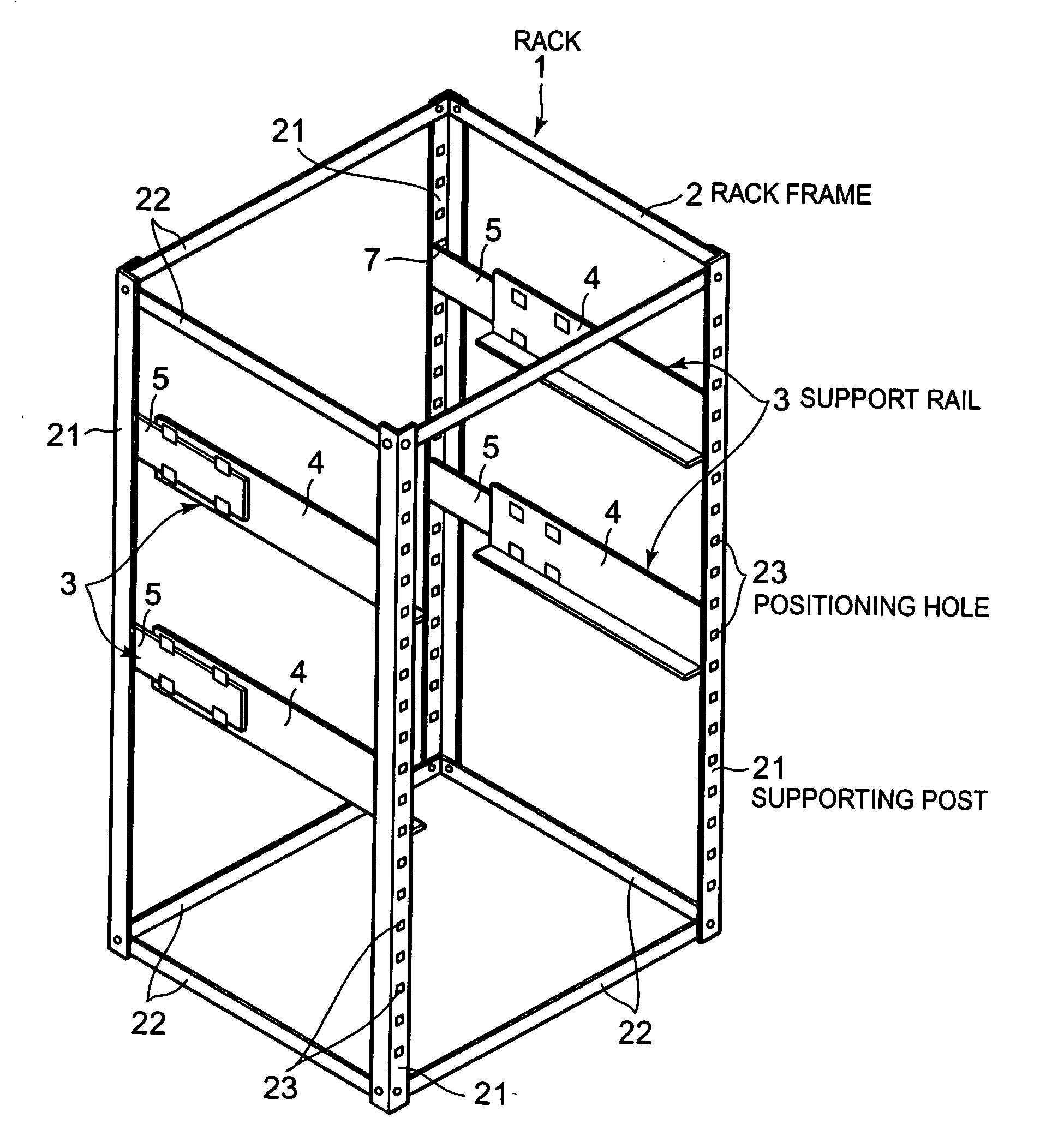
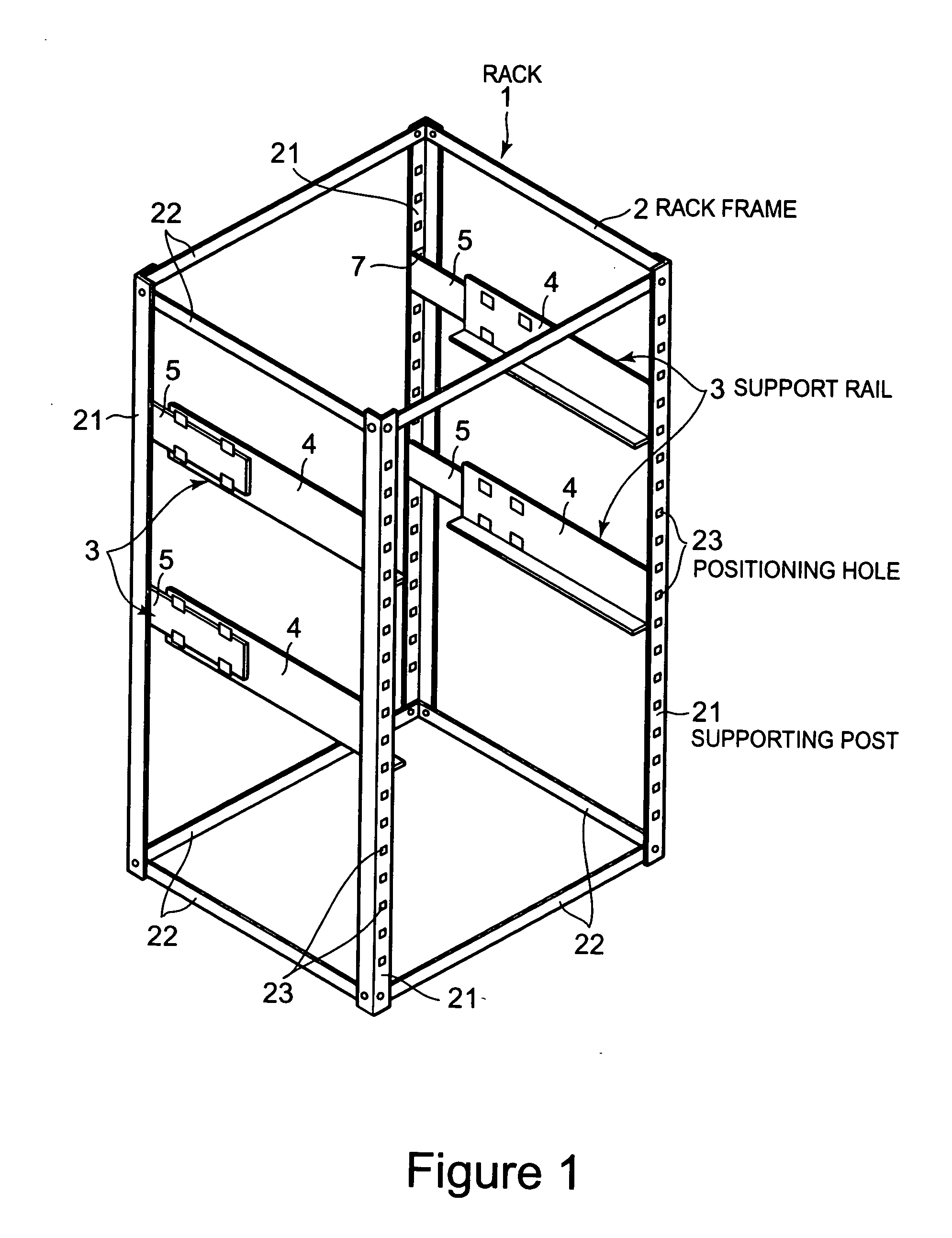
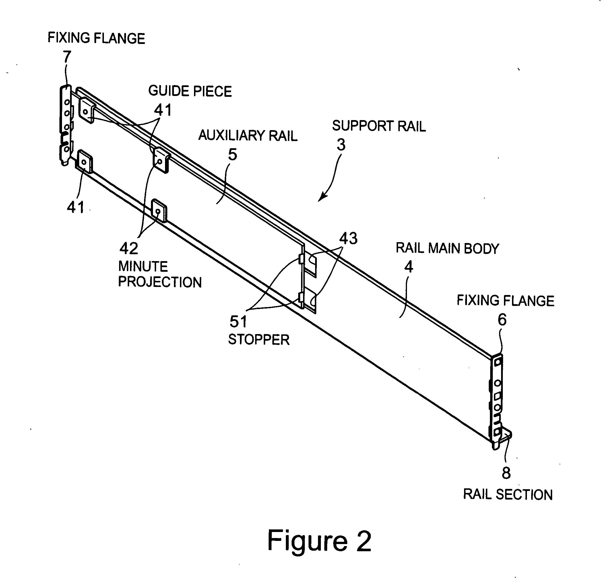
[0022] The present invention provides a rack system including a rack frame, a support rail which is fixable to the rack frame. A device is supportable by the support rail. Multiple positioning projections are provided on at least one of the rack frame and the support rail and each of which is insertable into positioning holes of different kinds provided in the other of the at least one of the rack frame and the support rail.

[0023] A fixing portion which may fix the support rail to the rack frame may include the multiple positioning projections.

[0024] The multiple positioning projections may include different height projections.

[0025] A lower projection of the multiple positioning projections may be wider than a higher projection of the multiple positioning projections.

[0026] When the lower projection fits into a positioning hole of one of the rack frame and the support rail of one kind, the higher projection may be inserted into a positioning hole of the one of the rack frame an...


PUM


Abstract

A rack system includes a rack frame, and a support rail which is fixable to the rack frame. A device is supportable by the support rail. Multiple positioning projections are provided on at least one of the rack frame and the support rail and each of which is insertable into positioning holes of different kinds provided in the other of said at least one of the rack frame and the support rail.

Description

BACKGROUND OF THE INVENTION [0001] 1. Technical Field [0002] The present invention relates to a rack system which can position support rails used to support various devices on rack frames, an adapter, a rack frame, a support rail, and a method of making a rack system. More particularly, the present invention relates to a rack which enables support rails to be mounted on rack frames having different specifications. [0003] 2. Background [0004] As a rack to mount various types of electronic devices, there is widely used a rack having support rails that are attached to rack frames in a fixed manner and devices are mounted on the support rails. This type of rack is useful especially in a case where multiple devices are mounted in a vertical array. [0005] In conventional racks, multiple pairs of support rails are attached beforehand to the right and left sides of a rack frame at prescribed vertical intervals and both sides of a device are each supported by a pair of support rails, whereby...

Claims


Application Information

Patent Timeline
Patent Type & Authority Applications(United States)
IPC IPC(8): A47B57/00A47F7/00
CPCA47B57/30A47B88/044H02B1/34H05K7/1421A47B88/43A47B57/10A47B57/48A47B81/06A47B96/14
Inventor IWAMOTO, MISA
Owner NEC CORP
Why Eureka
Try Eureka