
Target device

a target device and target technology, applied in the field of target devices, can solve the problems of difficult projectile attachment to the target, commonplace impact recording, and relatively stiff targets worn by users, and achieve the effects of improving the likelihood of a shot, easy configuration, and improved projectile attachmen

Inactive Publication Date: 2006-07-20
BELOG BARRY
View PDF18 Cites 4 Cited by
  • Summary
  • Abstract
  • Description
  • Claims
  • Application Information

AI Technical Summary

Benefits of technology

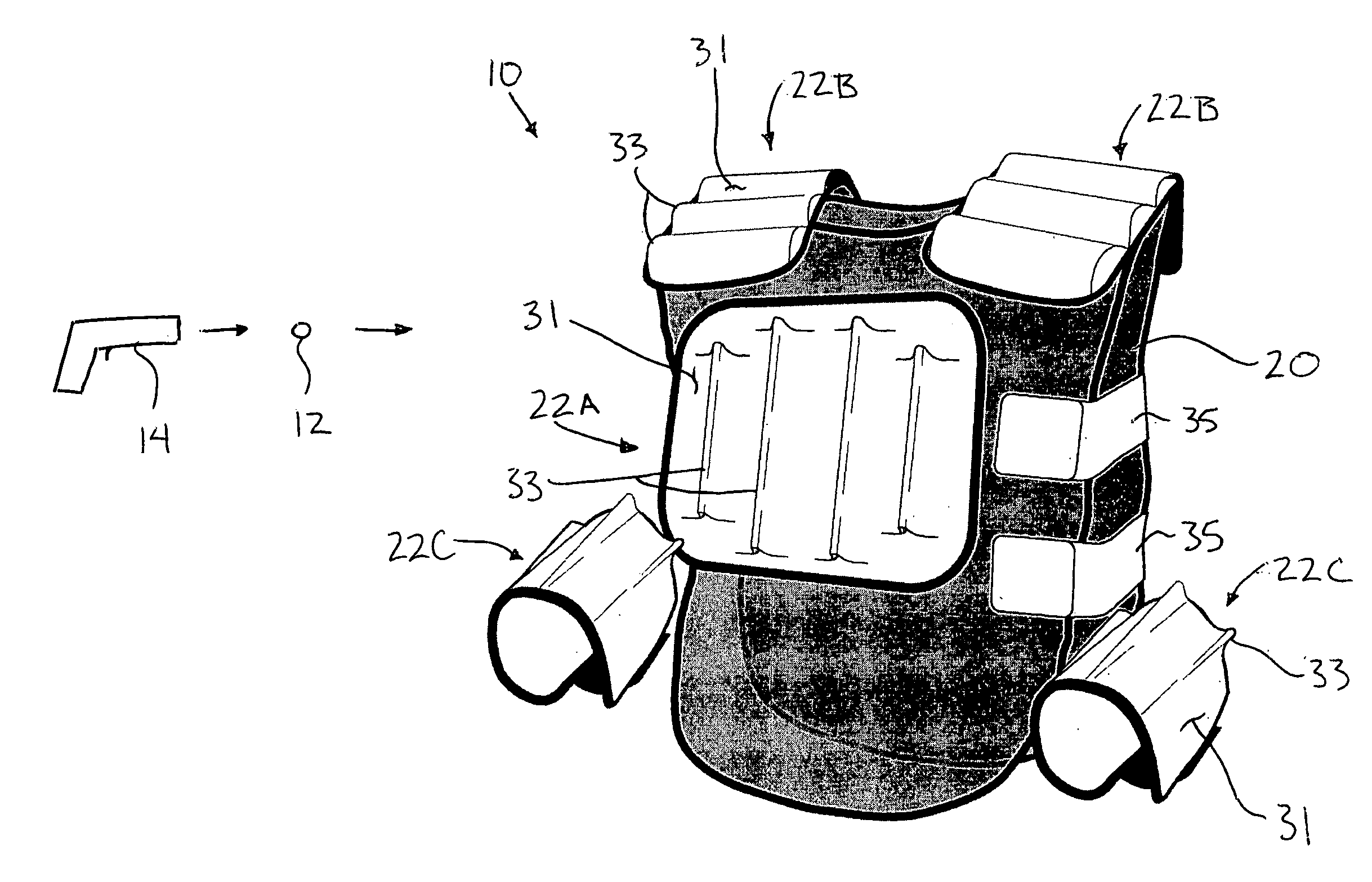
[0008] The irregular contour of the target surface results in a surface which lies at various angles, thus increasing the likelihood of a shot from any direction being perpendicular to a portion of the target surface for better attachment of the projectiles to the target surface in a hook and loop type game. The irregular surface can also be more readily configured into a flexible design allowing the user wearing the target device more range of movement and more comfort. The resiliency of the protrusions forming the irregular contour absorbs some of the impact force of the projectiles to further reduce the tendency for the projectiles to bounce off of the target surface.

Problems solved by technology

When firing hook and loop type projectiles, using a compressed air powered gun similar to what is described in U.S. Pat. No. 5,845,629 to Ratliff, the high velocities of the projectiles make it difficult for the projectile to attach itself to the target when fired at a sharp angle in relation to the surface instead of being normal thereto.
When playing a game in which the target device is worn by an opponent, it is common to be shooting projectiles at random angles relative to the surface of the target device and accordingly it is commonplace for impacts to be improperly recorded when playing due to the projectiles bouncing off of the targets.
Also, known targets to be worn by a user tend to be relatively stiff, which further encourages the occurrence of projectiles bouncing off of the targets.

Method used


Image

  • Target device
  • Target device
  • Target device

Examples


Embodiment Construction

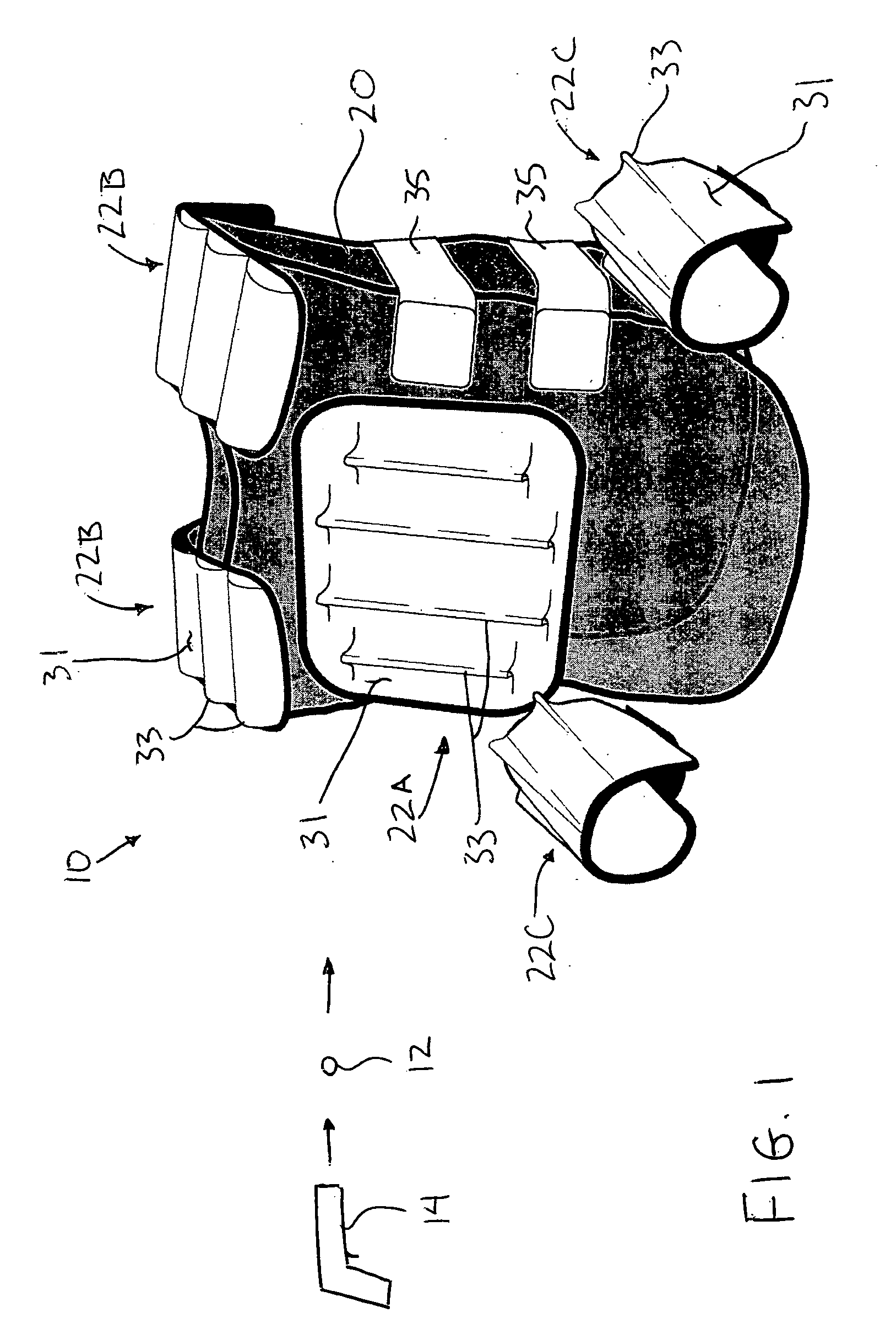
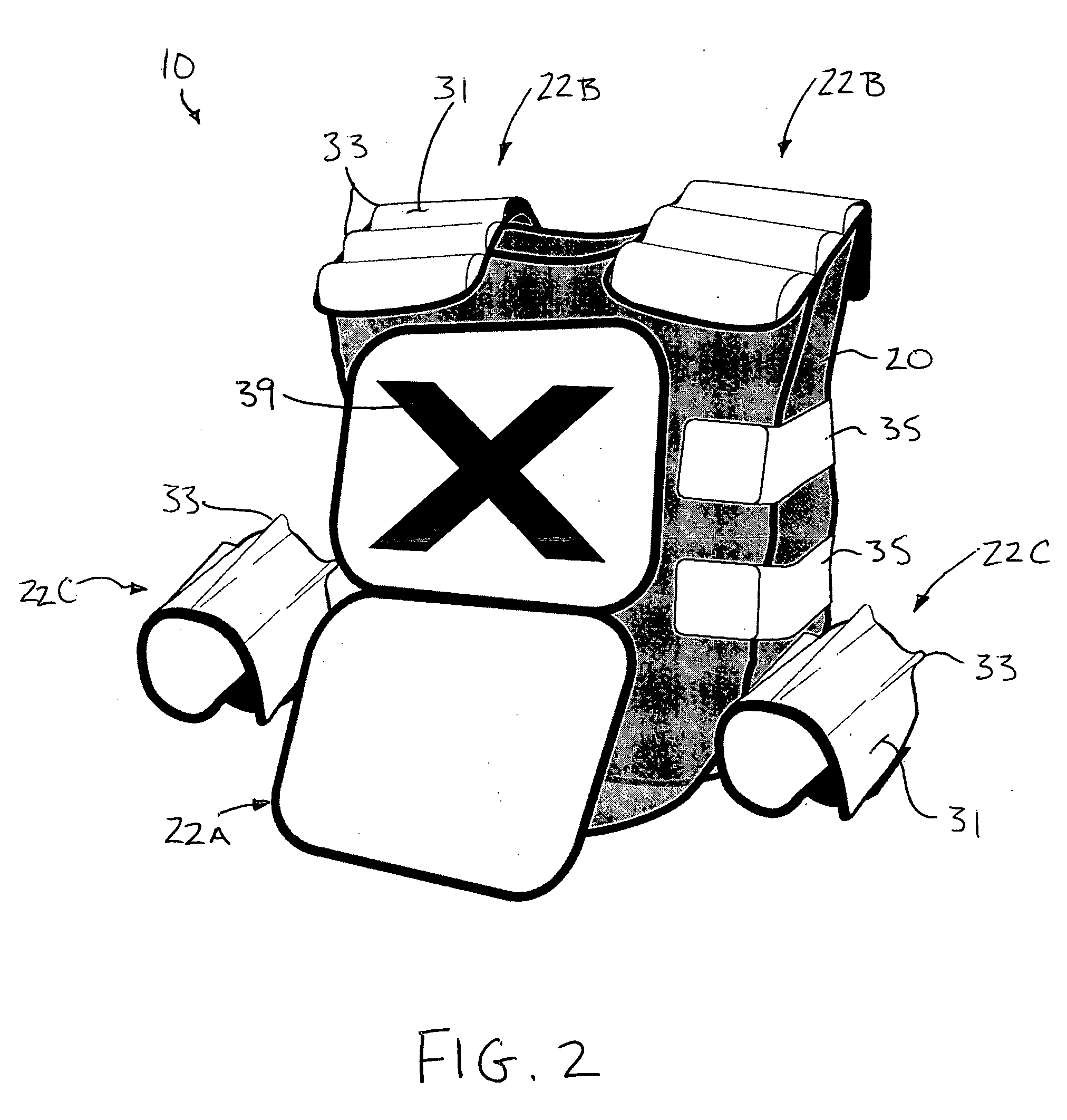
[0023] Referring to the accompanying drawings there is illustrated a target device generally indicated by reference numeral 10. The target device generally comprises a garment to be worn by a user in a game comprising projectiles and associated targets formed of hooks or loops of a hook and loop fastening system so that projectiles 12 remain attached to the target device 10 upon impact. The projectiles 12 each comprise a bead which is covered in loop material and which is suitably sized for being fired through the barrel of a comprised air powered gun 14 of the type commonly used for shooting paintball projectiles.

[0024] In all embodiments described herein, the device 10 includes a supporting element 20 which is worn by the user for supporting target panels 22 thereon. Each target panel 22 includes a substrate layer 30 which supports a target surface 31 of hooks of the hook and loop fastening system thereon. The target surface is irregular in contour, comprising a multifaceted surf...


PUM


Abstract

A target device is worn by a user in a game comprising projectiles covered with either hook or loop fasteners. The device includes a supporting element for being supported on the user which carries target panels having a target surface covered with hook or loop fasteners for mating connection with the projectiles. The target surface has an irregular in contour comprising various raised protrusions formed of resilient material. The irregular contour of the target surface results in a surface which lies at various angles, thus increasing the likelihood of a shot from any direction being perpendicular to a portion of the target surface for better attachment of the projectiles to the target surface in a hook and loop type game. The resilient nature of the protrusions also absorbs some of the impact force of the projectiles to reduce the tendency for the projectiles to bounce off of the target surface.

Description

[0001] This application claims the benefit under 35 U.S.C. 119(e) of U.S. provisional application Ser. No. 60 / 630,575, filed Nov. 26, 2004.FIELD OF THE INVENTION [0002] The present invention relates to a target device for being worn by a user in a game using projectiles which remain attached to the target device upon impact by hook and loop fasteners. BACKGROUND [0003] Various types of games are known using projectiles which remain attached to a target device upon impact. U.S. Pat. No. 5,221,092 to Simons Jr. et al. discloses on example of such a game wherein the target device comprises a coat type garment including various panels thereon upon which the projectiles can be attached on impact. When firing hook and loop type projectiles, using a compressed air powered gun similar to what is described in U.S. Pat. No. 5,845,629 to Ratliff, the high velocities of the projectiles make it difficult for the projectile to attach itself to the target when fired at a sharp angle in relation to...

Claims


Application Information

Patent Timeline
Patent Type & Authority Applications(United States)
IPC IPC(8): A63B63/00F41J3/00
CPCA63B71/12A63B2071/1208A63F9/0243F41H1/02F41H1/04F41J5/14
Inventor BELOG, BARRY
Owner BELOG BARRY
Learn More