
Tangential induction dynamoelectric machines

Inactive Publication Date: 2006-07-20
IVTSENKOV GENNADII
View PDF24 Cites 14 Cited by
  • Summary
  • Abstract
  • Description
  • Claims
  • Application Information

AI Technical Summary

Benefits of technology

[0019] Also, the experiments reveal that phases of both signals, induced in the semi-ring and radial conductor, are shifted on 180 degrees against each other. It shows possibility to create a multi-turn stator coil, which can be implemented in dynamoelectric machines based on the mentioned above effect of tangential induction.

Problems solved by technology

Also, Faraday's law does not deal with relative movement of a coil against magnetic field.
Moreover, there are a number of paradoxes in theoretical and practical electromagnetism.

Method used


Image

  • Tangential induction dynamoelectric machines
  • Tangential induction dynamoelectric machines
  • Tangential induction dynamoelectric machines

Examples


Embodiment Construction

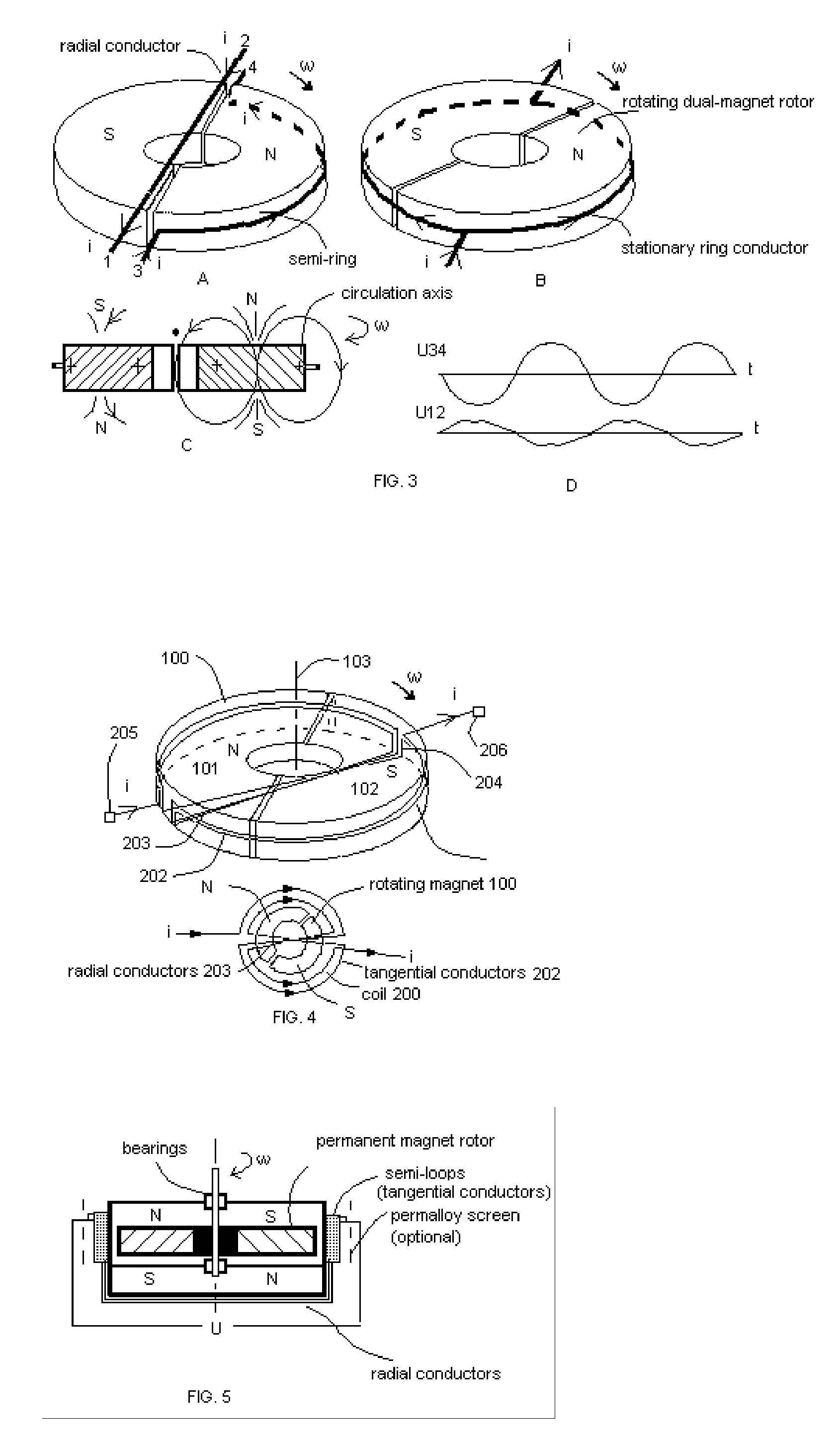
[0035] The scheme of the invention is shown in FIG. 4.

[0036] The tangential-induction alternating-current dynamoelectric machine—the preferable embodiment of the present invention—contains a permanent-magnet rotor 100 and a specially-organized multi-turn stator winding 200. The rotor 100 consist of a combined permanent-magnet ring containing two axially-polarized semi-ring parts 101 and 102 with opposite polarization. The rotor 100 rotates around axis 103 that is aligned with axis of symmetry of the magnet.

[0037] The stator 200 consists of multi-turn coil containing tangential semi-ring conductors (members) 202, radial conductors 203, short vertical conductors 204 and two terminals 205 and 206. The tangential conductors 202 are positioned on a plane crossing the middle of cylindrical surface of the magnet, where, according to the experiments, induced tangential e.m.f. is the maximal. The radial conductors 203 connect the opposite ends of the tangential conductors 202 in such a way...


PUM


Abstract

Novel class dynamoelectric machines utilizing “tangential induction” phenomenon—the specific e.m.f. induction, which appears in tangential conductors—is introduced. Alternating-current dynamoelectric machines of this invention house an axially-polarized multi-polar permanent magnet rotor and stator winding having tangentially arranged semi-ring conductors. The rotating permanent-magnet rotor induces current in tangential semi-ring conductors, which, according to Ampere law, could not produce a resistance moment applied to the rotor because the vector of conductor-field velocity is directed along the conductor, and, therefore, such vector orientation does not produce any tangential force. The invention has been successfully embodied in number of “tangential-induction dynamoelectric machines” including multi-phase ones. These dynamoelectric machines can be inverted and work as alternating-current asynchronic electric motors.

Description

FIELD OF THE INVENTION [0001] The present invention relates to the dynamoelectric and electric rotating machines, such as electric generators and motors utilizing a permanent magnet rotor. More particularly, the invention pertains to utilize the phenomenon of “tangential induction” in dynamoelectric machines. The present invention also relates to homopolar electric generators. BACKGROUND OF THE INVENTION [0002] This application is the corresponding non-provisional one related to the provisional application No. 60 / 593,445 filed Jan. 14, 2005. [0003] Dynamoelectric machines with permanent-magnet rotor are used for many applications. Such machines, for example, the generators described in U.S. Pat. No. 3,237,034 issued to S. Krasnow Feb. 22, 1966, U.S. Pat. No. 3,334,254 issued to Kober et al. Aug. 1, 1967 and U.S. Pat. No. 5,767,601 issued to Uchiyama Jun. 16, 1998, usually utilize a radial-polarized multi-pole permanent magnet and a number of solenoid windings axially oriented on the...

Claims


Application Information

Patent Timeline
Patent Type & Authority Applications(United States)
IPC IPC(8): H02K21/12
CPCH02K21/24H02K31/02
Inventor IVTSENKOV, GENNADII
Owner IVTSENKOV GENNADII
Learn More