Articulating arm

a technology of articulating arms and arm joints, applied in the field of articulating arms, can solve the problems of difficult to repeat and accurately place manual methods, complex approaches that require expensive and complex imaging or computational systems to determine, and severe clinical limitations of both approaches

Active Publication Date: 2006-07-20
NEURONETICS
View PDF99 Cites 101 Cited by
  • Summary
  • Abstract
  • Description
  • Claims
  • Application Information

AI Technical Summary

Benefits of technology

[0009] Just one embodiment of the invention includes a device, method and system for positioning a treatment instrument with respect to a patient. The novel device includes a holder for securing the treatment instrument (e.g., a magnetic stimulation device used for transcutaneous magnetic stimulation treatment of depression). The holder allows the treatment instrument to move about the patient. The device also includes a first arm that is coupled to the holder, and a vertical support that is coupled to the first arm. The first arm is substantially transverse to the vertical support, and may rotates about the vertical support in a horizontal axis. Such rotation, as well as movement and rotation of other components with respect to each other may be facilitated by a ball bearing construction.
[0013] The holder also may have a rotating assembly and a downrod that connects the rotating assembly to the first arm. The holder's curved portion may move in an arcuate motion through the rotating assembly. The rotating assembly may be capable of rotating 360 degrees with respect to the first arm, where such rotation is facilitated by a ball bearing construction. Also, the curved portion of the holder may have a radius greater than a patient's head, so as to prevent the curved portion from undesirably contacting the patient's head. Also, the curved portion may be locked as it moves through the rotating assembly.

Problems solved by technology

The manual approaches are very accurate and the complex approaches require expensive and complex imaging or computational systems to determine three dimensional spatial coordinates for positioning reference.
Both approaches have severe clinical limitations.
The manual methods do not provide a convenient means for repeated and accurate placement, while the three dimensional spatial methods based on imaging modalities are expensive, time consuming, and not conducive to clinical use.
The shortcomings of such manual methods is that movement of the device is constrained, making it difficult to determine the proper treatment location.
Also, even once the proper location of the treatment area is located, maintaining the device at the proper location is cumbersome.
Of course, this approach requires careful registration of the headgear during subsequent therapy sessions, which is crude, imprecise, and highly operator dependent.
Moreover, such an approach still requires accurate coil placement and a mechanism for holding the coil in place.
On the other hand, the Brainsight™ System developed by Rogue Research, Inc. of Montreal, Canada and distributed by Magstim is complex and is designed primarily for research purposes.
While this approach is useful for research purposes, it is highly impractical and complex and is thus not usable in general clinical practice.
Moreover, such techniques have generally been used to overlay coordinate systems onto images and not for identifying particular treatment positions for specific therapies.
Also, other complex methods include the use of robotic, machine-controlled arms for positioning the treatment device with respect to the patient and holding the device in place during treatment.
While these techniques provide controlled movement and placement of the coil, they are quite expensive and do not provide for repeatable placement of the coil with respect to a particular patient's head in a clinical setting.

Method used


Image

  • Articulating arm
  • Articulating arm
  • Articulating arm

Examples


Embodiment Construction

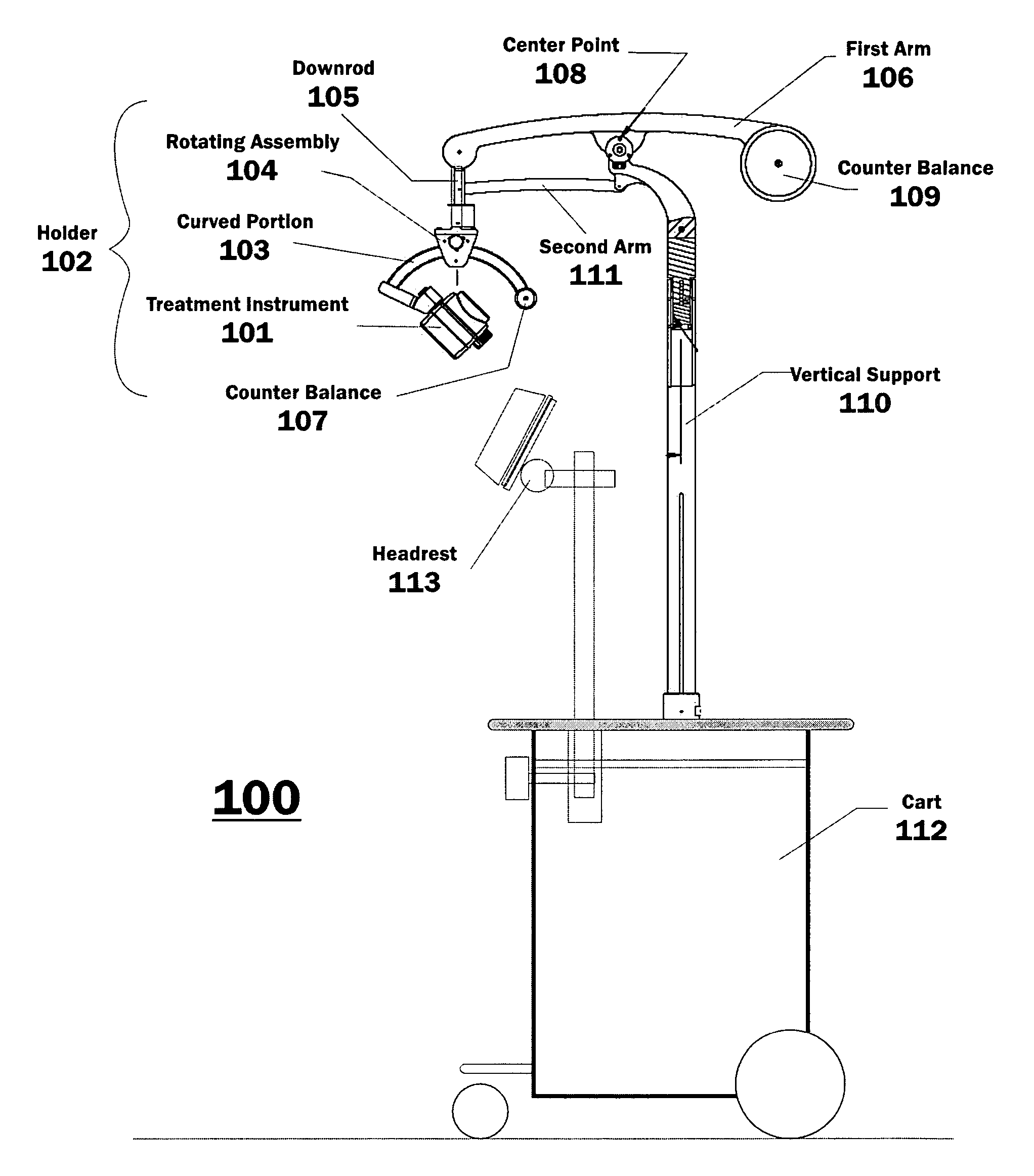
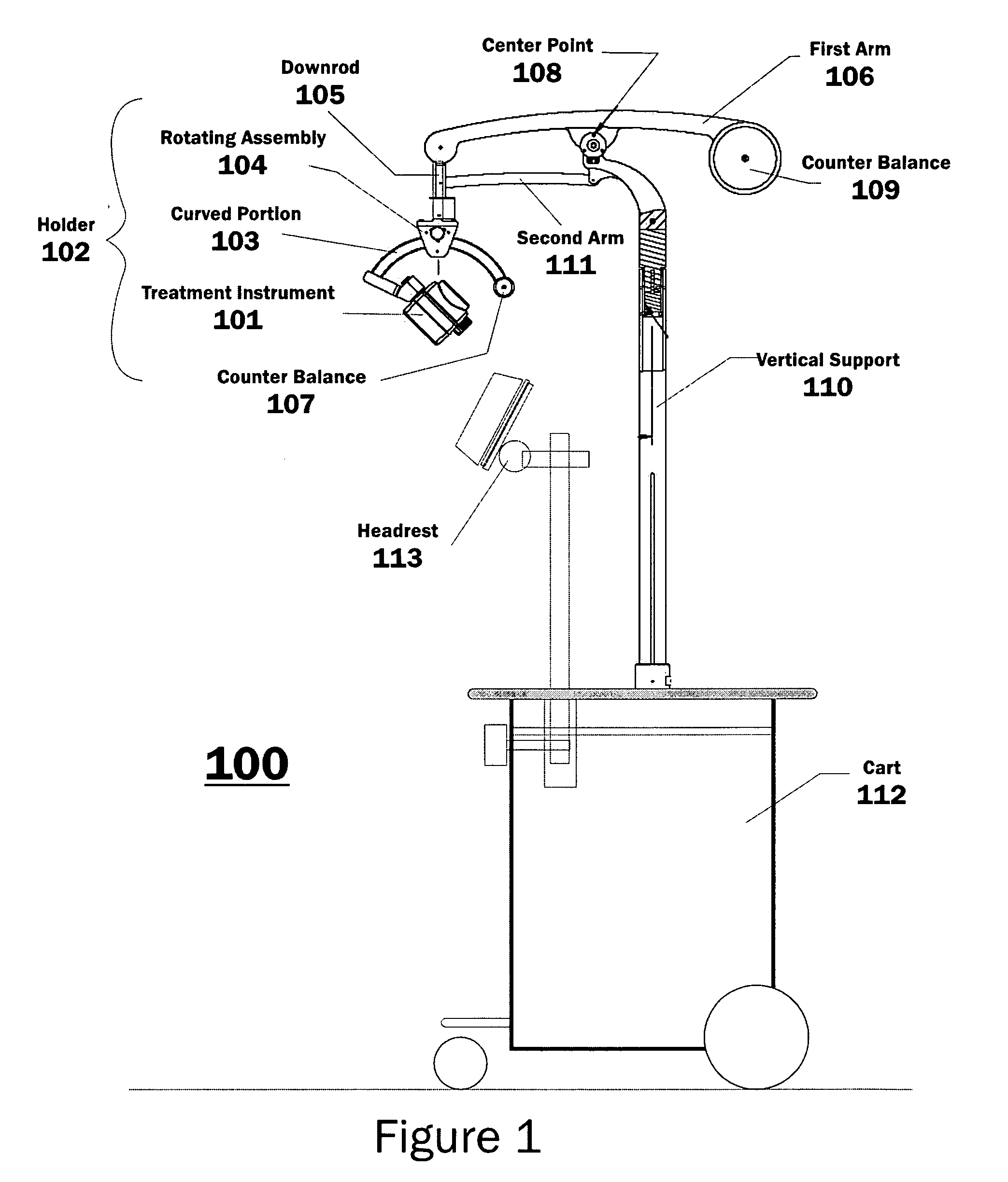
[0025] A detailed description of an illustrative embodiment of the present invention will now be described with reference to FIGS. 1-5. Although this description provides a detailed example of a possible implementation of the present invention, it should be noted that these details are intended to be exemplary and in no way delimit the scope of the invention.

[0026] For example, although the invention is discussed in the context of a TMS magnet, it should be appreciated that the treatment instrument may be any treatment instrument. For example, the treatment instrument may be a magnetic stimulation device used for transcutaneous magnetic stimulation treatment of depression. Furthermore, although the device is described with reference the movement of a treatment instrument, it should be appreciated that the device may be used to move and position things other than instruments for the treatment of patients.

[0027]FIG. 1 illustrates a side view of a device 100 for positioning a treatme...


PUM


Abstract

Just one embodiment of the invention includes a device, method and system for positioning a treatment instrument with respect to a patient. The novel device includes a holder for securing the treatment instrument (e.g., a magnetic stimulation device used for transcutaneous magnetic stimulation treatment of depression). The holder allows the treatment instrument to move about the patient. The device also includes a first arm that is coupled to the holder, and a vertical support that is coupled to the first arm. The first arm is substantially transverse to the vertical support, and may rotates about the vertical support in a horizontal axis. Such rotation, as well as movement and rotation of other components with respect to each other may be facilitated by a ball bearing construction.

Description

CROSS-REFERENCE TO RELATED PATENT APPLICATION [0001] The subject matter disclosed herein is related to the subject matter disclosed in the following copending application: U.S. application Ser. No. 10 / 752,164 (Attorney Docket Number NNI-0011), which was filed Jan. 6, 2004, and which is incorporated herein by reference.FIELD OF THE INVENTION [0002] The invention relates to a method and apparatus for positioning a medical device. More specifically, the invention contemplates a positioning system and method for precisely positioning a transcranial magnetic stimulation coil at a treatment location for a patient. BACKGROUND OF THE INVENTION [0003] Current techniques for positioning medical treatment devices (e.g., magnets for Transcranial Magnetic Stimulation (TMS) studies) typically are simple manual methods or complex robotic approaches designed for research. The manual approaches are very accurate and the complex approaches require expensive and complex imaging or computational system...

Claims


Application Information

Patent Timeline
Patent Type & Authority Applications(United States)
IPC IPC(8): A61N2/00A61B46/23
CPCA61B19/26A61B2019/264A61N2/006A61B90/50A61B2090/504
Inventor JULIANA, VINCENT A.RIEHL, MARK EDWARDPILLUTLA, RAVI
Owner NEURONETICS
Why Eureka
Try Eureka