Surgical access port

a surgical and access port technology, applied in the field of surgical devices, can solve the problems of unsightly scars, increased trauma, and extended recovery tim

Inactive Publication Date: 2006-07-20
MASSACHUSETTS UNIV OF +1
View PDF69 Cites 190 Cited by
  • Summary
  • Abstract
  • Description
  • Claims
  • Application Information

AI Technical Summary

Benefits of technology

[0005] The invention features a surgical access port that allows a surgeon's hand or instrument to access a patient's body cavity through a sealed opening. The access port includes two parts, a wound retractor and a sealing sleeve. The wound retractor is designed to retract the edges of an incision made into a body cavity into an opening, and to seal around the edges of the opening, thereby forming a gas-tight connection between the body cavity and the interior of the access port. The sealing sleeve connects to the wound retractor external to the body cavity and provides a path for a surgeon to insert his hand through the opening formed by the wound retractor. The sealing sleeve seals around a surgeon's arm or a surgeon's glove, when the surgeon's hand is inserted into the body cavity, and seals the opening when the surgeon's hand is removed from the access port. Thus, the port provides hand access to the body cavity, and prevents gases in the body cavity, such as insufflation gases, from escaping into the surroundings.
[0010] In another embodiment, the access port includes a flap valve that connects to the open end of the flexible sleeve and extends into the channel. The flap valve seals the channel when there is a positive pressure differential between the channel and the surroundings. A pair of drawstrings can be attached to opposite ends of the flap valve and pull the ends in opposite directions to enhance the sealing ability of the flap valve.
[0018] In one embodiment, the sealing sleeve further includes an outer sleeve surrounding the flexible sleeve and forming a chamber therebetween, and an inlet port for inflating the chamber. Inflating the chamber compresses together a central portion of the flexible sleeve, thereby sealing the channel. The drawstrings attach to opposite sides of the central portion of the flexible sleeve, pulling the sides in opposite directions toward the outer sleeve, thereby imparting a preferred flattened geometry to the central portion of the inner sleeve and enhancing the seal.
[0019] In another embodiment, the mechanism further includes a flap valve that connects to the open end of the flexible sleeve and extends into the channel. The flap valve seals the channel when there is a positive pressure differential between the channel and the surroundings. The drawstrings attach to opposite ends of the flap valve, pulling the ends in opposite directions, enhancing the sealing ability of the flap valve.
[0022] Since the edges of the incision are retracted by simply inflating the collars, the wound retractor is easy to use. Furthermore, the wound retractor provides a seal around the perimeter of a retracted wound, from the inner abdominal wall to the surface of the skin. The seal prevents infection and provides a gas-tight connection between the body cavity and the remainder of the access port.
[0023] In the sealing sleeve portion of the access port, the flap valve and the inner sleeve, which is compressed by the inflatable chamber, provide a gas-tight seal around a surgeon's arm when the surgeon's hand is inserted into a patient's body cavity. This seal prevents insufflation gases from escaping. The effectiveness of this seal is improved by the drawstrings.

Problems solved by technology

While large incisions simplify access to the body cavity during a surgery, they also increase trauma, require extended recovery time, and can result in unsightly scars.
While minimally invasive surgical methods overcome certain drawbacks of traditional methods, there are still various disadvantages.
In particular, there is limited tactile feedback from the manipulated tissue to the surgeon hands.

Method used


Image

  • Surgical access port
  • Surgical access port
  • Surgical access port

Examples


Embodiment Construction

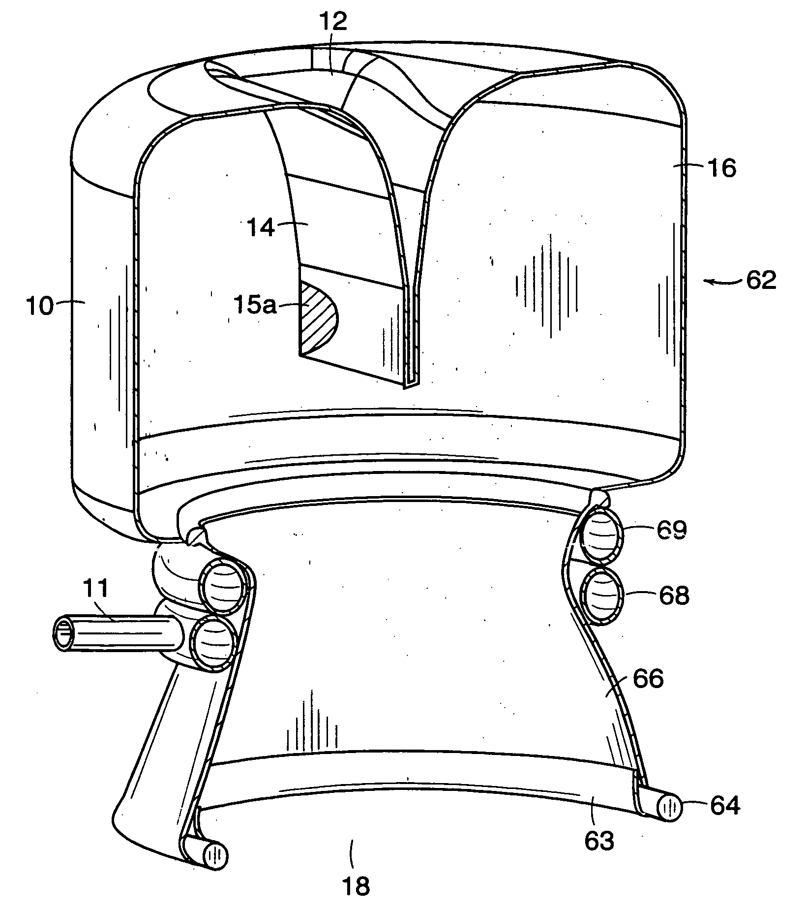
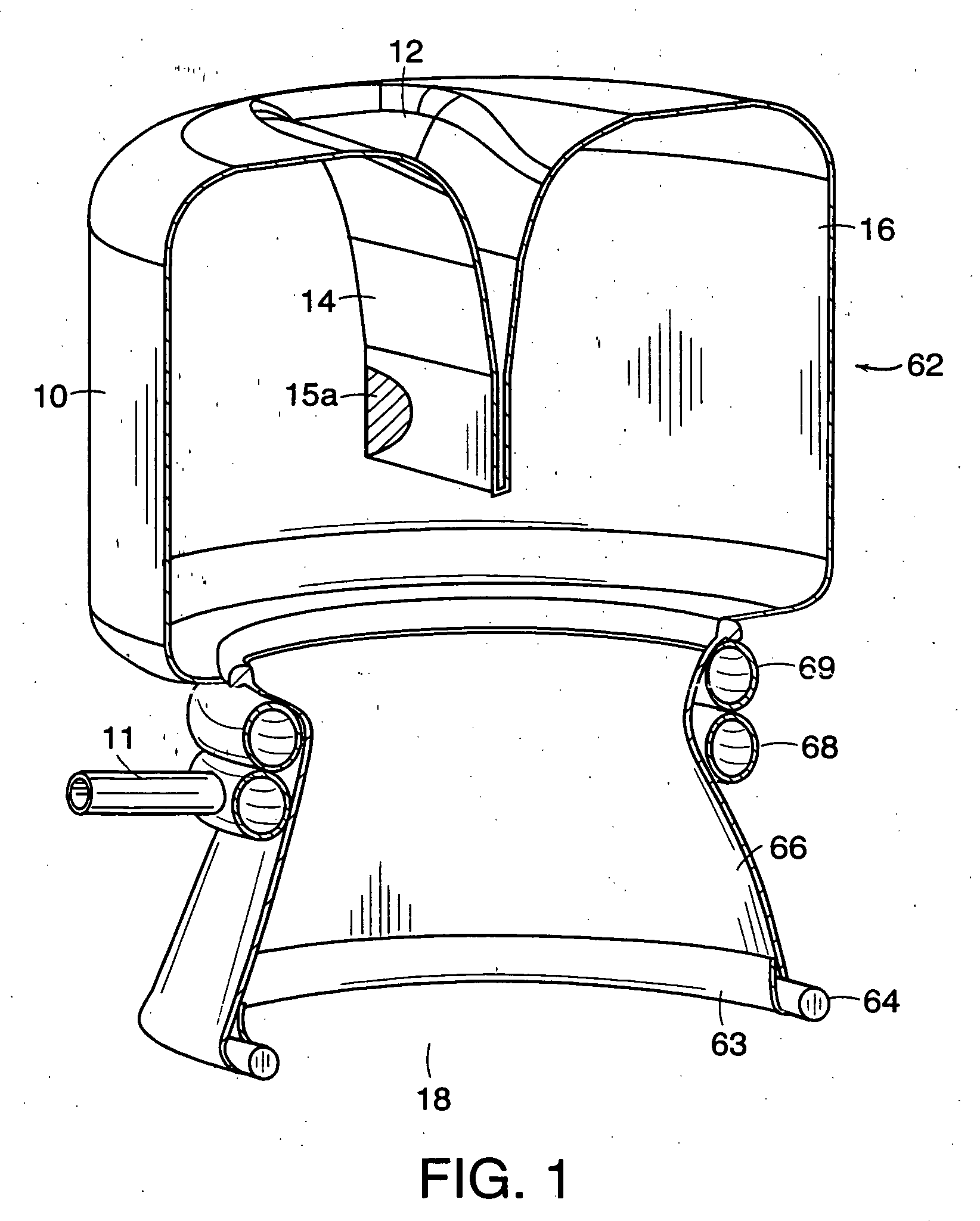
[0039] The surgical access port is best described as having two parts, a wound retractor and a sealing sleeve.

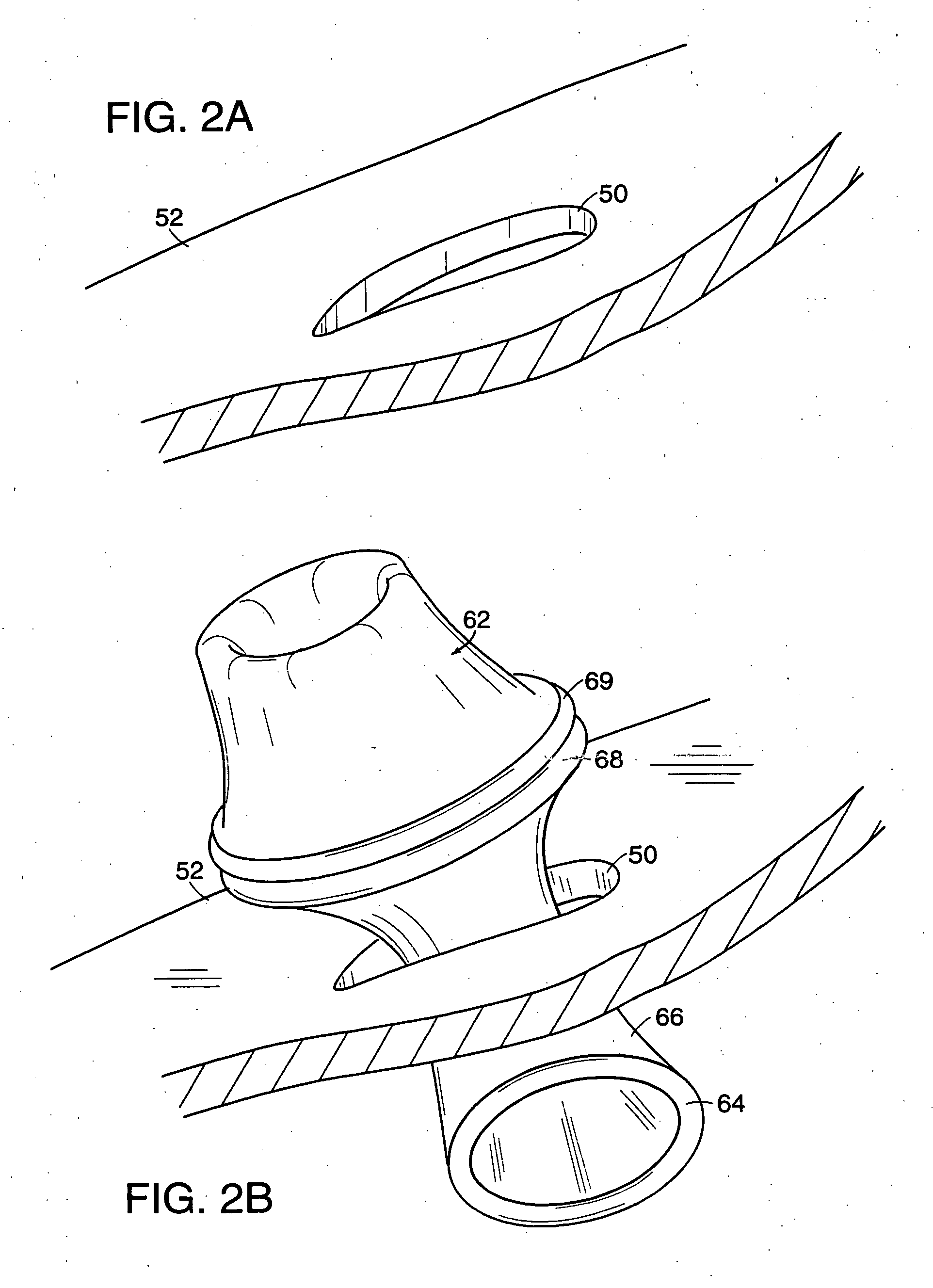
[0040] The wound retractor includes a flexible tubular skirt having a first end reinforced with a stiff ring so that the first end is maintained in an open orientation, and a second end surrounded by one or more inflatable collars. The reinforced first end is inserted into the body cavity through an incision, providing a channel through the skirt from the outside to the inside of the body cavity. During use, the collars are inflated, thereby drawing out skirt within the incision and pulling the reinforced first end of the skirt tight against the inner wall of the patient's skin. As a result, the edges of the incision are retracted into an opening and the skirt seals around the perimeter of the opening along the inner abdominal wall to the outer surface of the skin.

[0041] A sealing sleeve is attached to the wound retractor portion above the inflatable collars. The sealing s...


PUM


Abstract

A device for retracting edges of an incision in a surface to form an opening including: a flexible, tubular skirt having an upper end, a lower end, and a channel therebetween; a ring connected to the lower end of the skirt for maintaining the lower end in an open configuration and defining an exit opening to the channel; and an inflatable collar connected to the skirt and surrounding the upper end. The ring is designed to fit through the incision and remain under the surface when it is oriented parallel to surface. The collar, when inflated, maintains the upper end in an open configuration and defines an entry opening to the channel. During use, the ring is inserted through the incision and the collar is inflated while remaining outside of the incision, thereby drawing the skirt against the edges of the incision and retracting the edges of the incision to form the opening. The retracting device can be included in a surgical access port, which further includes a flexible sleeve connected to at least one of the inflatable collar and the skirt, extending the channel from the exit opening of the skirt to an open end of the flexible sleeve distal to the skirt. The device can include a light source in the vicinity of the exit opening.

Description

BACKGROUND OF THE INVENTION [0001] This invention relates to the field of surgical devices. More particularly, the invention relates to a surgical access port, which provides a gas-tight seal for a hand or instrument to be inserted through the opening into a patient's body cavity. [0002] Abdominal surgery typically involves an incision in the abdominal wall large enough to accommodate a surgeon's hands, multiple instruments, and illumination of the body cavity. While large incisions simplify access to the body cavity during a surgery, they also increase trauma, require extended recovery time, and can result in unsightly scars. In response to these drawbacks, minimally invasive surgical methods have been developed. [0003] In minimally invasive abdominal surgery, several smaller incision are made into the abdominal wall. One of the openings is use to inflate the abdominal cavity with gas, which lifts the abdominal wall away from underlying organs and provides space to perform the desi...

Claims


Application Information

Patent Timeline
Patent Type & Authority Applications(United States)
IPC IPC(8): A61B1/32A61B17/00A61B17/02A61B17/34A61B19/00A61B19/04
CPCA61B17/00234A61B17/0293A61B17/3423A61B17/3431A61B17/3462A61B19/04A61B19/38A61B2017/00557A61B2017/3419A61B2017/3449A61B2017/3484A61B2019/5206A61B42/00A61B90/40A61B2090/306A61B42/10A61B90/30
Inventor BEANE, RICHARDEK, STEVENIEMANN, ALLISON C.CARROLL, MAUREEN E.HASSLINGER, RANDALL J.STAMM, EDWARD I. JR.VERDURA, JAVIER
Owner MASSACHUSETTS UNIV OF
Why Eureka
Try Eureka