
Glove with flow-through pocket

Inactive Publication Date: 2006-07-27
SEIRUS INNOVATIVE ACCESSORIES
View PDF14 Cites 8 Cited by
  • Summary
  • Abstract
  • Description
  • Claims
  • Application Information

AI Technical Summary

Benefits of technology

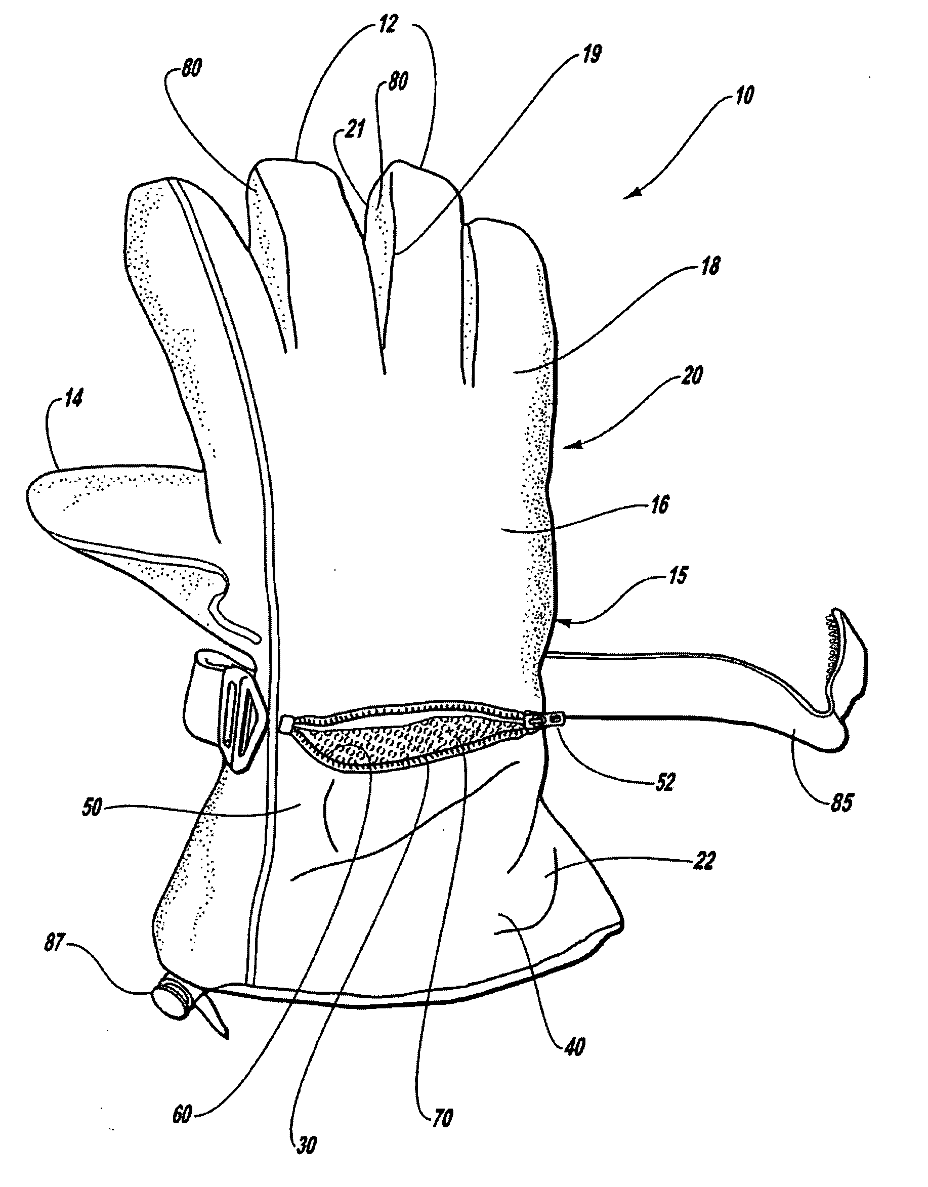
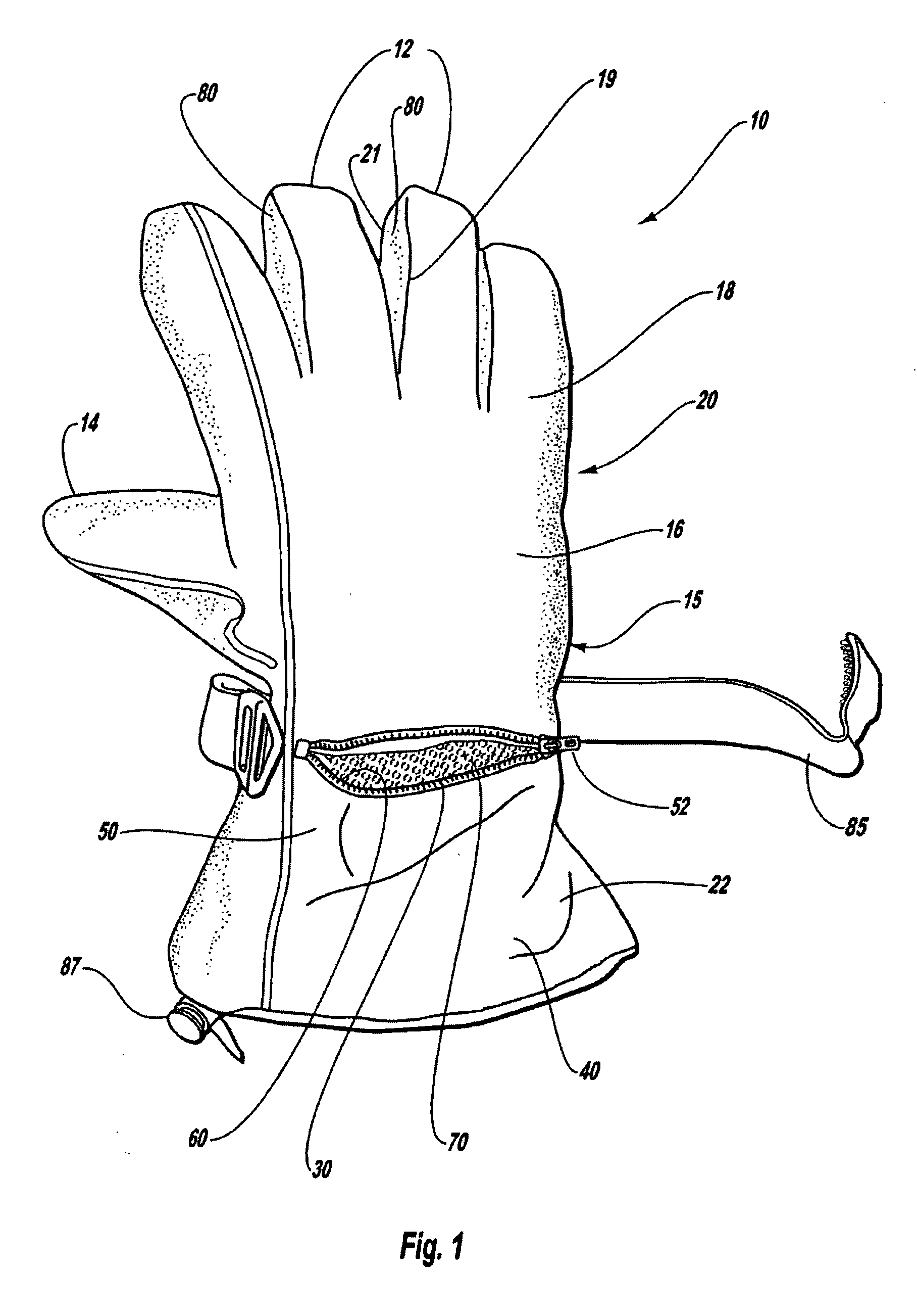
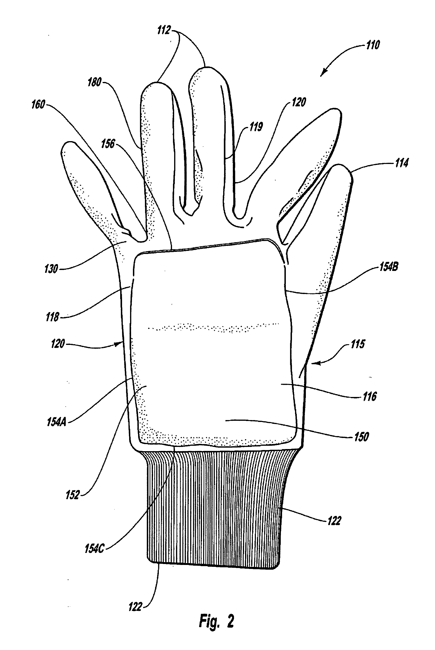
[0008] A second embodiment of the glove has a web-like pouch that is secured to the back-hand portion of the glove for removable insertion of a similar heat-insulating barrier. Alternative embodiments of the heat-insulating barrier are contemplated and include barriers constructed of single layers rather than multiple layers and multiple barriers that are made from individual barriers that are stacked in layers, one upon the other. The ability to add and remove any number of barriers enables one to convert an otherwise cold weather glove, typically used in the cold months of winter, into a moderate weather glove that can also be used in the months of spring, thereby obviating the need to purchase or otherwise carry two sets of gloves for use in different temperature environments. A still further embodiment includes a heat-generating layer positioned adjacent the heat-insulating barrier or positioned in between any two individual heat-insulating barriers that are stacked in layers.
[0009] Another embodiment of the invention is a glove having an insulation pocket for removable insertion of an insulator. The glove includes: a glove body having a back-hand portion formed from a first material; an insulator for insulating the back of the hand, said insulator being formed from a heat-insulating material; and pocket means formed relative to said back-hand portion for receiving said insulator. The pocket means has: a first opening for removably positioning said insulator therein, said pocket means including a pouch formed from a second material different than said first material, said pouch being secured to said glove body and sized to receive said insulator; and a second opening, wherein opening said first opening and said second opening and removing said insulator permits increased cooling from the back of the hand.

Problems solved by technology

Such devices, however, require periodic replenishment of the fuel or power for the external source of heat.

Method used


Image

  • Glove with flow-through pocket
  • Glove with flow-through pocket
  • Glove with flow-through pocket

Examples


Embodiment Construction

[0017] Referring to FIGS. 1 and 3, a glove 10 is provided that is configured to fit a human hand. The glove 10 has, generally, fingers, a thumb 14, a palm portion 15, a back-hand portion 16 and a wrist portion 22. A heat-insulating barrier 100 is removably inserted into a pouch means 50 that is secured to the back-hand portion 16 of the glove 10. The heat-insulating barrier 100 is secured specifically to the back-hand portion 16 of the glove 10 as it is believed that heat loss from the back-side of the hand is responsible for the fingers becoming cold in cold weather environments. For example, it is believed that heat is lost through the back of the hand while the hand grips a ski pole when skiing.

[0018] The heat-insulating barrier 100 is constructed of heat-insulating material, such as, for example, closed-cell neoprene with fleece laminated therewith, and is adapted for insertion into the pouch means 50 when the fingers of the hand are cold and for removal from the pouch means 50...


PUM


Abstract

A glove having a heat insulating barrier is disclosed. The heat insulating barrier is removably inserted into a zippered pocket or a weblike pouch, the pocket or pouch being positioned proximate the back of a user's hand. the heat insulating barrier acts to selectively reduce heat conduction from the back side of the hand, thereby allowing the user's hand or hands to remain warm in cold environments. The ability to stack a varying number of heat insulating layers in the pouch or pocket further allows the user to selectively control the warmth of the hand as the ambient temperature fluctuates during use. The zippered pocket or weblike pouch can have first and second opening to permit increased cooling through the back portion of the glove.

Description

CROSS-REFERENCE TO RELATED APPLICATIONS [0001] This application is a continuation-in-part of application Ser. No. 10 / 314,029, filed Dec. 6, 2002, which claims the benefit of Provisional Application No. 60 / 338,103, filed Dec. 7, 2001, both of which are incorporated herein by reference in their entireties.BACKGROUND OF THE INVENTION [0002] 1. Field of the Invention [0003] The invention is directed to the field of apparel and, more particularly, to cold-weather hand coverings like a glove having a selectively shaped insulating barrier that is removably into the hand coverings to selectively control heat conduction from the hand coverings. [0004] 2. Description of the Prior Art [0005] It is known in the prior art to provide pouch-like pockets on the surface of gloves or mittens to provide an external source of heat for warming the hand in cold weather environments. Such prior art devices are disclosed, for example, in U.S. Pat. No. 1,970,081 (Eisendrath), in U.S. Pat. No. 4,543,671 (Mon...

Claims


Application Information

Patent Timeline
IPC IPC(8): A41D19/00A41D19/015
CPCA41D19/01529A41D19/01594
Inventor CAREY, MICHAEL J.EDWARDS, JOSEPH H.
Owner SEIRUS INNOVATIVE ACCESSORIES
Learn More