Liquid transport cavity saw blade

Inactive Publication Date: 2008-05-08
CUTTING EDGE DESIGNS
View PDF14 Cites 3 Cited by
  • Summary
  • Abstract
  • Description
  • Claims
  • Application Information

AI Technical Summary

Benefits of technology

[0009] The present invention exhibits improved cooling of a saw blade retained in proper cutting alignment by lubricating saw guide supports, thereby advancing attempts to reduce saw blade thickness. In particular, the present invention, when used to cut Southern Yellow Pin

Problems solved by technology

The guide support assembly is required because the circular saw blades have been reduced to a thickness rendering them incapable of maintaining a generally planar configuration during cutting, thereby making them unsuitable for use without auxiliary side support.
Unfortunately, as saw blade thickness decreases more support must be provided by the bearing surface of the guide support against the saw blade which generates greater friction therebetween.
This increase in friction can lead to excessive heating of the saw blade which, in turn, can ultimately lead to carbide insert teeth breakage, sawing deviation, guide pad wear, and saw blade da

Method used


Image

  • Liquid transport cavity saw blade
  • Liquid transport cavity saw blade
  • Liquid transport cavity saw blade

Examples


Embodiment Construction

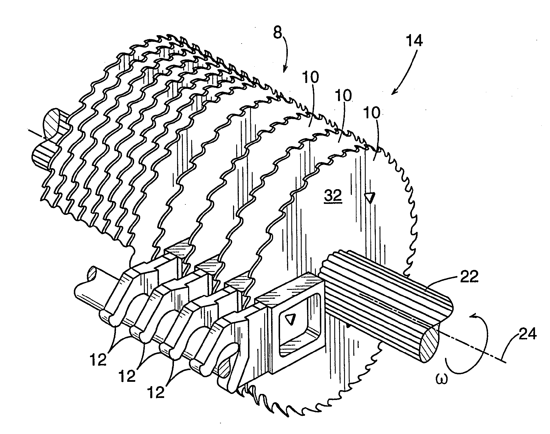
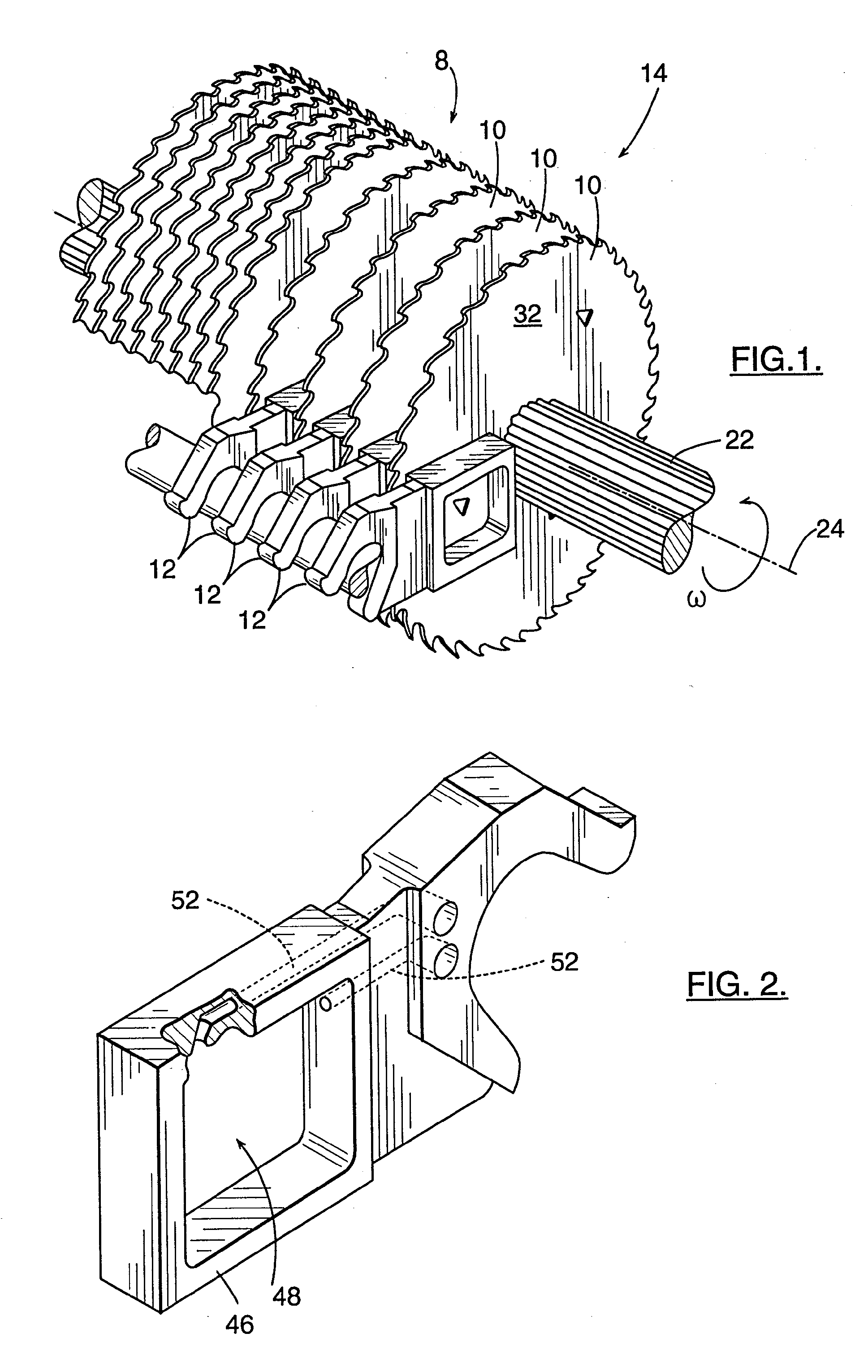
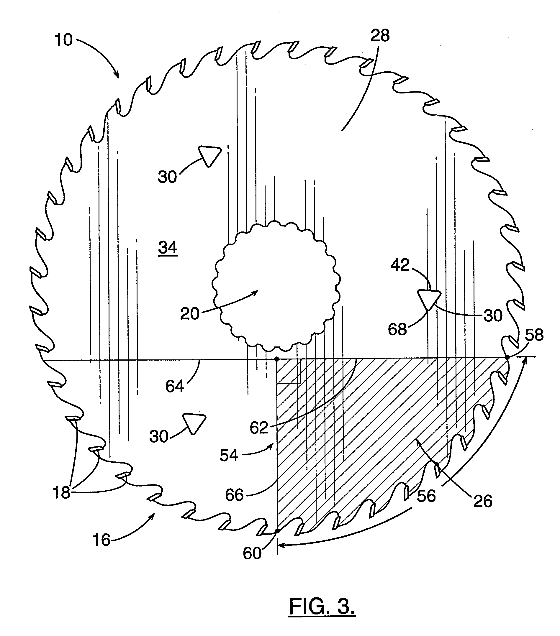
[0020] Referring now to the drawings, the present invention relates broadly to a saw arrangement 8 including the combination of a circular saw blade 10 and a lubricating guide support assembly 12. As shown in FIG. 1, this combination can be repeated to form what is commonly known as a horizontal gang saw 14 in the lumber industry. In each combination, and with reference to FIG. 3, the saw blade 10 includes a cutting edge 16 comprised of carbide insert teeth 18 for cutting during rotation of the saw blade 10. The saw blade 10 also includes a central opening 20 by which the saw blade 10 is mounted to an arbor 22 extending along an axis 24 that simultaneously drives each saw blade 10 by rotation in a circumferential direction ω. The rotation of the saw blades 10 generates the cutting action of the gang saw 14 for the cutting of lumber in a cutting area (generally indicated at 26).

[0021] Preferably each circular saw blade 10 includes a planar saw body 28 having a diameter of 18 and ½ i...


PUM

PropertyMeasurementUnit
Fractionaaaaaaaaaa
Fractionaaaaaaaaaa
Angleaaaaaaaaaa

Abstract

A saw arrangement includes the combination of a saw blade and a lubrication guide support. The saw blade has a planar saw body and a cutting edge defining a rotational direction for cutting. The planar saw body has a planar annular section with oppositely facing parallel surfaces and an axial thickness therebetween. The planar annular section also defines a plurality of cavities therein. The lubricating guide support has a bearing surface adjacent the saw body for proper alignment of the saw blade during cutting. The guide support contains liquid exposed to the saw body at the bearing surface whereby liquid is applied to the saw body as it passes by the bearing surface. The cavities pass by the exposed liquid during movement of the saw blade. The cumulative opening area of the plurality of cavities equals approximately six percent of a cutting triangle of the circular saw blade.

Description

CROSS REFERENCE TO RELATED APPLICATIONS [0001] This application is a continuation-in-part of U.S. patent application Ser. No. 10 / 604,144, filed Jun. 27, 2003, pending, which '144 application is incorporated herein by reference, and which '144 application is a continuation of U.S. patent application Ser. No. 09 / 906,523, filed Jul. 16, 2001, now U.S. Pat. No. 6,705,188, which is incorporated herein by reference, and which '523 application is a continuation of international patent application no. PCT / US00 / 00365, filed Jan. 7, 2000, abandoned, which international application was published in English under PCT Article 21(2), which international application is incorporated herein by reference, and which international application, in turn, is a continuation of U.S. patent application Ser. No. 09 / 232,401, filed Jan. 15, 1999, now U.S. Pat. No. 6,050,163, which '401 application further is incorporated herein by reference.BACKGROUND OF INVENTION [0002] The present invention relates to a saw a...

Claims


Application Information

Patent Timeline
IPC IPC(8): B26D7/08
CPCB23D59/02B27B5/34B23D61/025Y10T83/263
Inventor GRAVELY, ROBERT WAYNELEE, MICHAEL MONROE
Owner CUTTING EDGE DESIGNS
Why Eureka
Try Eureka