Internal cooling of power cables and power umbilicals

Active Publication Date: 2014-11-13
NEXANS
View PDF8 Cites 2 Cited by
  • Summary
  • Abstract
  • Description
  • Claims
  • Application Information

AI Technical Summary

Benefits of technology

[0011]One objective of the present invention is to improve the cooling of power cables and power umbilicals, especially when above sea level. A further objective is to provide cooling wit

Problems solved by technology

The transfer of electrical power through a power cable results in generation of heat within the cable.
A special problem area is powe

Method used


Image

  • Internal cooling of power cables and power umbilicals
  • Internal cooling of power cables and power umbilicals
  • Internal cooling of power cables and power umbilicals

Examples


Embodiment Construction

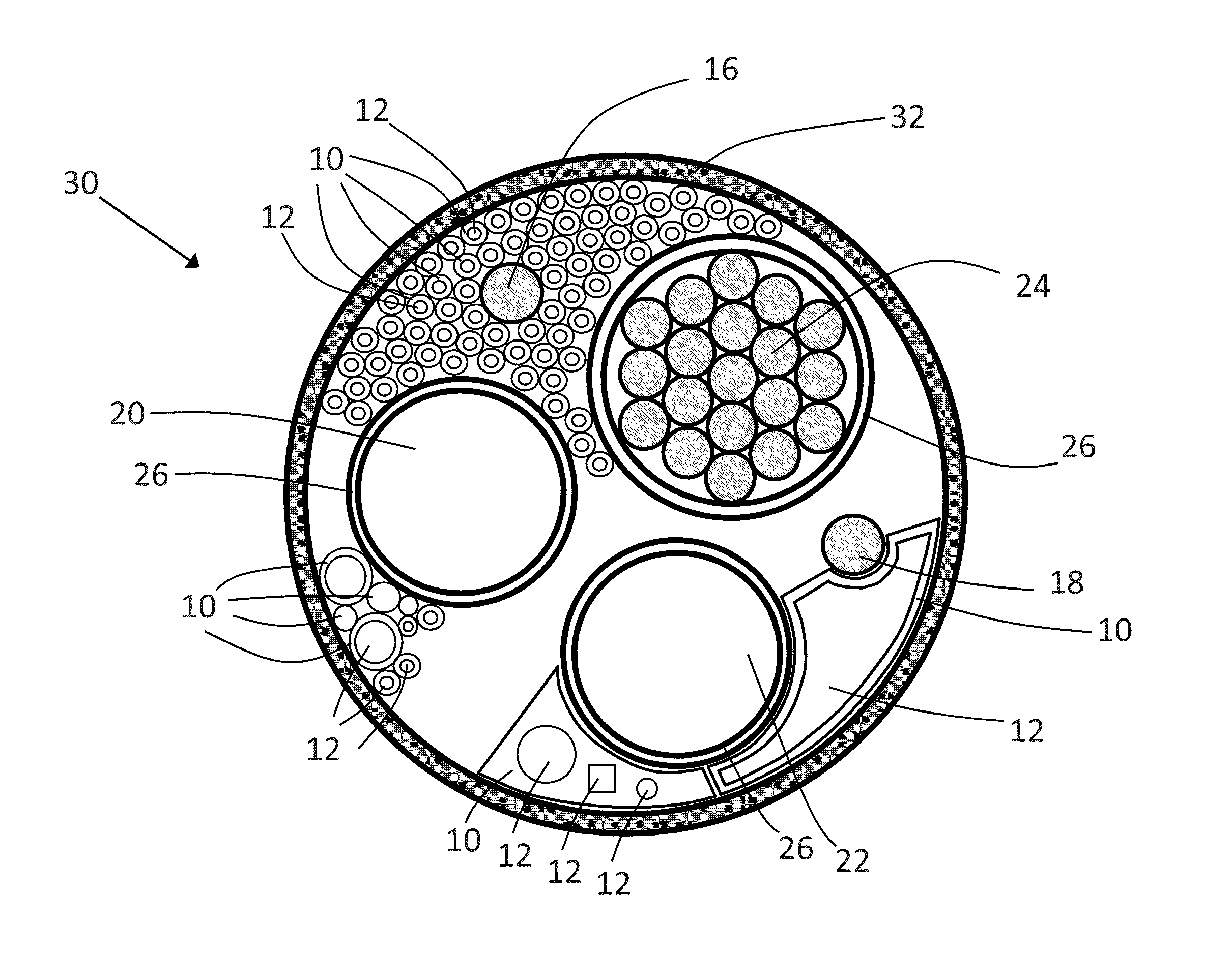
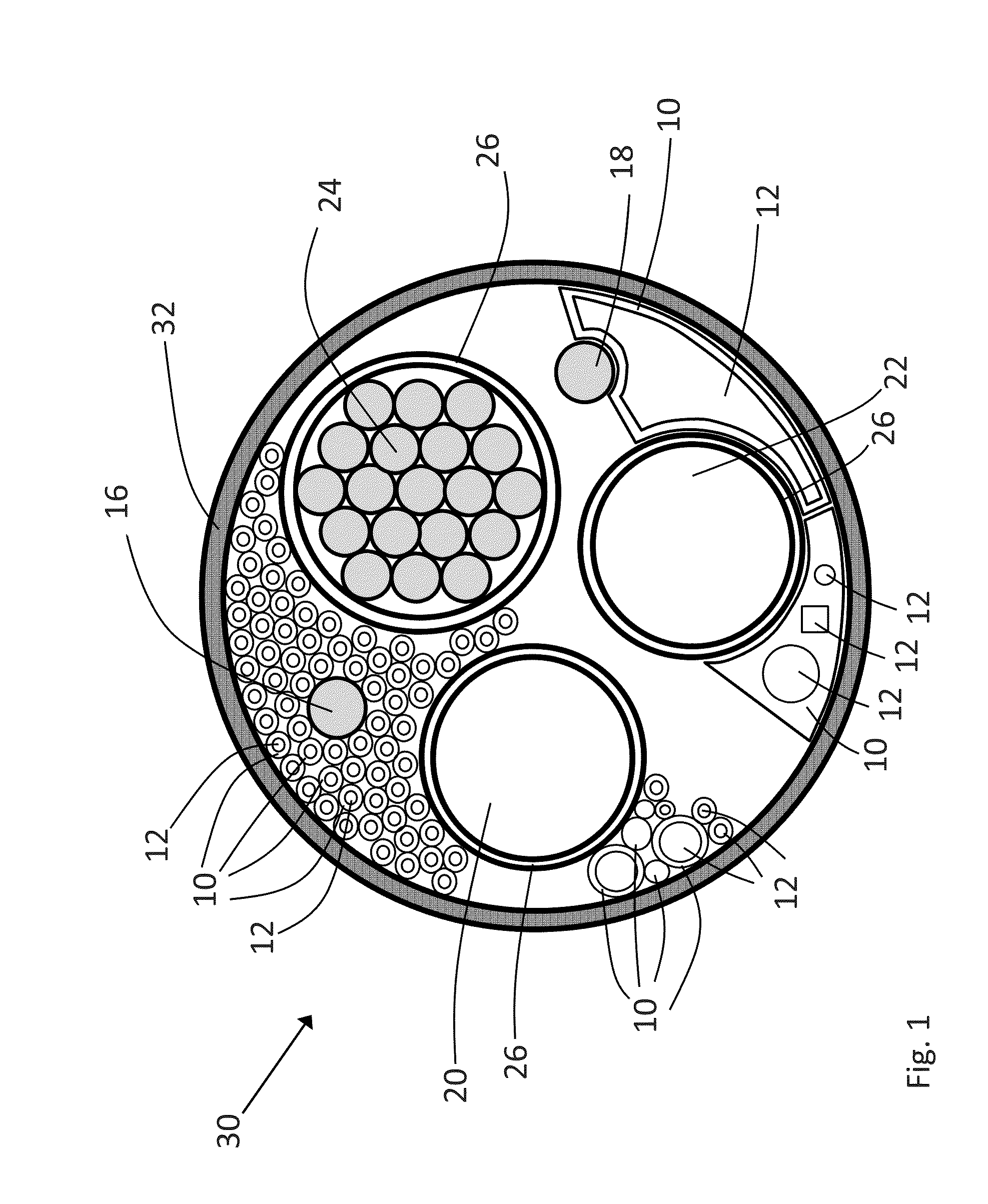
[0032]The present invention will be discussed in further detail with reference to the enclosed drawings. It should be noted that the drawings illustrate a number of possible embodiments, but that the present invention may be utilized in a number of power cable designs including power umbilicals and that the drawings are only schematic illustrations showing examples of such cables.

[0033]FIG. 1 illustrates schematically a cross sectional view through an power umbilical cable 30 with an outer shell 32, and conductor elements 20, 22 and 24 arranged therein. The purpose of the conductor elements is to transfer electrical power. The conductor elements can be solid conductors or comprise a plurality of conductor elements 24 stranded together and surrounded by a sheet layer 26. The conductor elements 20 and 22 are similarly covered by a sheet layer 26. The number of conductor elements and the design of each of the elements can be freely selected based on the intended use of the power umbili...


PUM


Abstract

A power cable (30, 130, 230, 330, 430, 530) includes an outer sheath (32), at least one conductor element (20, 22, 24, 220, 320, 420, 520) arranged within the outer sheath and one or more filler elements (10, 210, 310,410, 510) arranged within the outer sheath. At least one of the filler elements is hollow such that a cooling fluid can be passed through the filler element.

Description

RELATED APPLICATION[0001]This application claims the benefit of priority from Norwegian Patent Application No. 2013 0655, filed on May 8, 2013, the entirety of which is incorporated by reference.BACKGROUND[0002]1. Field of the Invention[0003]The present invention relates to a power cable, especially a power cable or power umbilical cable in need of internal cooling.[0004]2. Description of Related Art[0005]The transfer of electrical power through a power cable results in generation of heat within the cable. The present invention relates to transfer of heat caused by the electrical power away from the insulating-, semi conductive- and protective layers surrounding the power conductor(s) in a cable (power cable or power umbilical). A special problem area is power cables arranged inside guide tubes at platforms or other installations above sea level where the guide tube may be filled with air. This section represents a thermal bottleneck and is often the dimensioning factor for the whol...

Claims


Application Information

Patent Timeline
IPC IPC(8): H01B7/42
CPCH01B7/423F16L11/22H01B7/045H01B9/00H01B7/14H01B7/421H01B7/425
Inventor KARLSEN, JAN ERIKBADOWSKI, RAYMOND ALEXANDERHALL, JON-ARNE
Owner NEXANS
Why Eureka
Try Eureka