Vapor chamber

Pending Publication Date: 2021-04-29
ABB (SCHWEIZ) AG
View PDF2 Cites 3 Cited by
  • Summary
  • Abstract
  • Description
  • Claims
  • Application Information

AI Technical Summary

Benefits of technology

[0009]It is therefore an object of the invention to provide a solution for overcoming at least one disadvantage of the prior art at least in part. It is especially an o

Problems solved by technology

This leads to higher heat loss densities which require advanced cooling concepts.
In fact, traditional Aluminum or Copper heat sinks are limited by heat flux densities of 10 W/

Method used


Image

  • Vapor chamber
  • Vapor chamber
  • Vapor chamber

Examples


Embodiment Construction

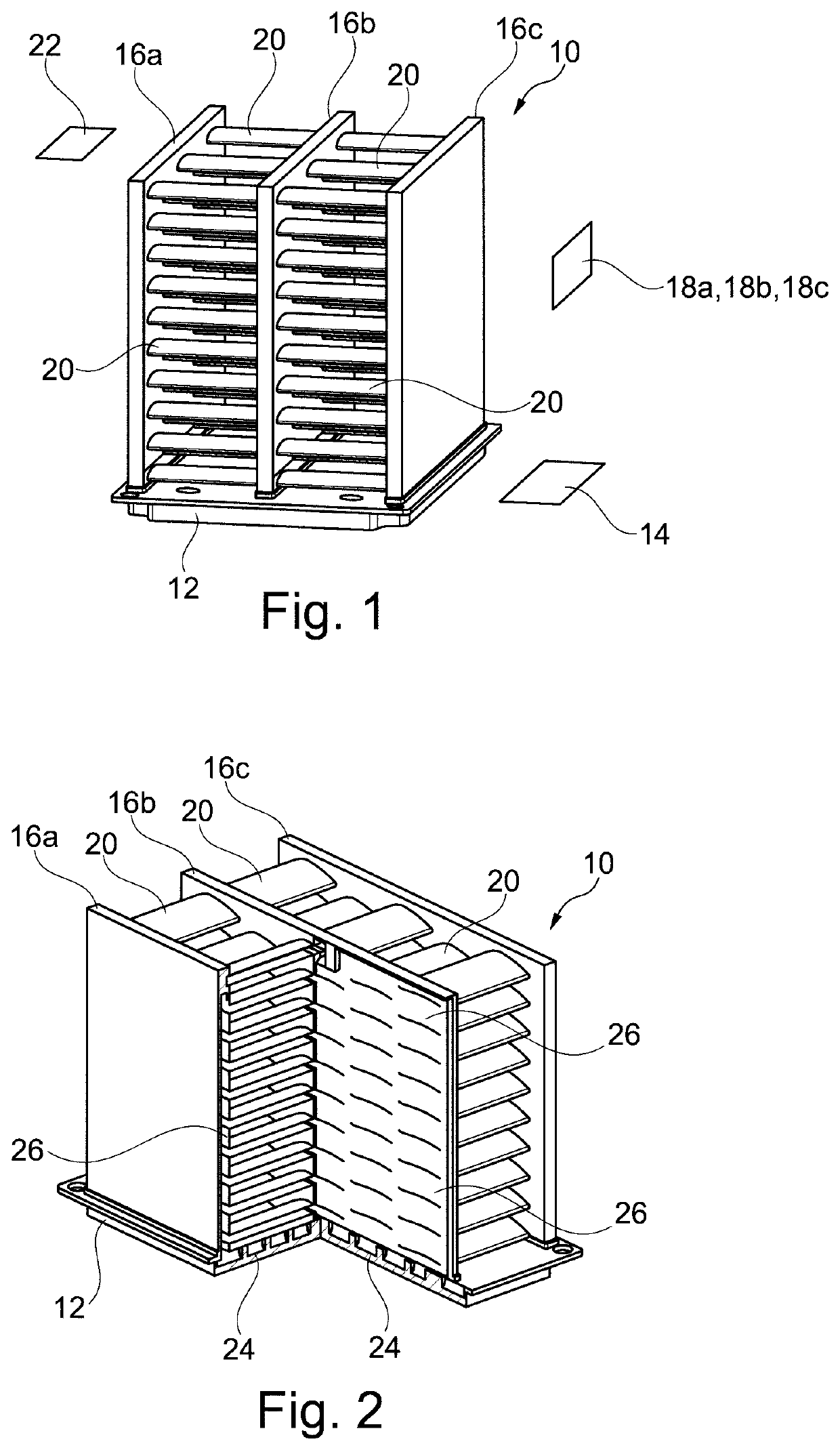
[0069]FIG. 1 shows an embodiment of a vapor chamber 10 for cooling a heat source such as for cooling a power semiconductor module, wherein the heat source is not shown as such. The vapor chamber 10 may thus be arranged in thermal contact with the heat source such as with a part of a power semiconductor module, such as with a baseplate, in order to cool the latter.

[0070]The vapor chamber 10 comprises an evaporator 12 proceeding in a first plane 14. The first plane 14 thus defines the orientation of the evaporator 12 which generally may have a plate-like form. The vapor chamber 10 according to FIG. 1 further comprises three condensers 16, i.e. condensers 16a, 16b and 16c which each are internally coupled to the evaporator 12. The condensers 16a, 16b and 16c proceed in respective planes 18a, 18b and 18c, wherein the planes 18a, 18b and 18c are arranged perpendicular to the first plane 14 and are thus arranged parallel to each other. The planes 18a, 18b and 18c are identical and compris...


PUM


Abstract

The application relates to a vapor chamber for cooling a heat source, the vapor chamber includes an evaporator proceeding in a first plane and the vapor chamber includes at least a first condenser and a second condenser, wherein the first and second condenser are internally coupled to the evaporator, wherein the first condenser proceeds in a second plane, and the second condenser proceeds in a third plane, wherein the second plane and the third plane are arranged in an angle to the first plane, wherein at least one air fin is provided, wherein the at least one air fin proceeds in a fourth plane, and wherein the first condenser and the second condenser are internally coupled to the air fin, and wherein the evaporator, the first condenser, the second condenser and the air fin form a common internal volume.

Description

TECHNICAL FIELD[0001]The invention relates to vapor chamber. The present invention particularly refers to a vapor chamber for dissipating heat from a heat source, such as from an electronic device, especially from a power semiconductor module having an improved cooling capacity. The present invention further relates to an arrangement of a power semiconductor module and such a vapor chamber, wherein the vapor chamber is configured for cooling the power semiconductor module.BACKGROUND ART[0002]Power semiconductor modules are generally widely known in the art. Power semiconductor modules may comprise a baseplate that may carry an electric circuit comprising one or more power semiconductor devices. For protection of the power semiconductor module, the latter may be encapsulated at least in part by an encapsulation material. The encapsulation may be formed in a transfer molding process. Transfer molding is a manufacturing process where the encapsulation material may be forced into a mold...

Claims


Application Information

Patent Timeline
IPC IPC(8): H01L23/427F28D15/04
CPCH01L23/427F28D15/04F28D15/0266F28D15/043H01L23/3672H01L21/4882F28F1/26F28F1/24F28D15/0233F28F3/048F28F1/32F28F2250/02F28F2210/02H05K7/20309
Inventor TORRESIN, DANIELEAGOSTINI, BRUNOPETROV, ANDREY
Owner ABB (SCHWEIZ) AG
Why Eureka
Try Eureka