Pipe wrench assembly

a technology of pipe wrenches and wrenches, which is applied in the direction of pliers, manufacturing tools, etc., can solve the problems of inability to clamp or fix tubular or cylindrical work pieces with such wrenches, work pieces may slip easily out of the wrenches, etc., and achieves the effect of ensuring the clamping effect and easy and convenient use for users

Inactive Publication Date: 2006-07-27
WANG CHING SHU
View PDF12 Cites 26 Cited by
  • Summary
  • Abstract
  • Description
  • Claims
  • Application Information

AI Technical Summary

Benefits of technology

[0007] Therefore, it is a primary objective of the present invention to provide an improved pipe wrench assembly. With an insert pin and a guide plate together, the first and second movable wrench members can automatically produce a horizontal clamping movement when the pipe wrench is clamped and released, and thus a user needs not to adjust the angle between the first and second movable wrench members. The present invention provides an easy and convenient way for users to use a pipe wrench and assures the clamping effect.

Problems solved by technology

If a user exerts a force on the wrench to clamp a tubular or cylindrical work piece, then the work piece may slip out of the wrench easily, and the tubular or cylindrical work piece cannot be clamped or fixed by such wrench.

Method used


Image

  • Pipe wrench assembly
  • Pipe wrench assembly
  • Pipe wrench assembly

Examples


Embodiment Construction

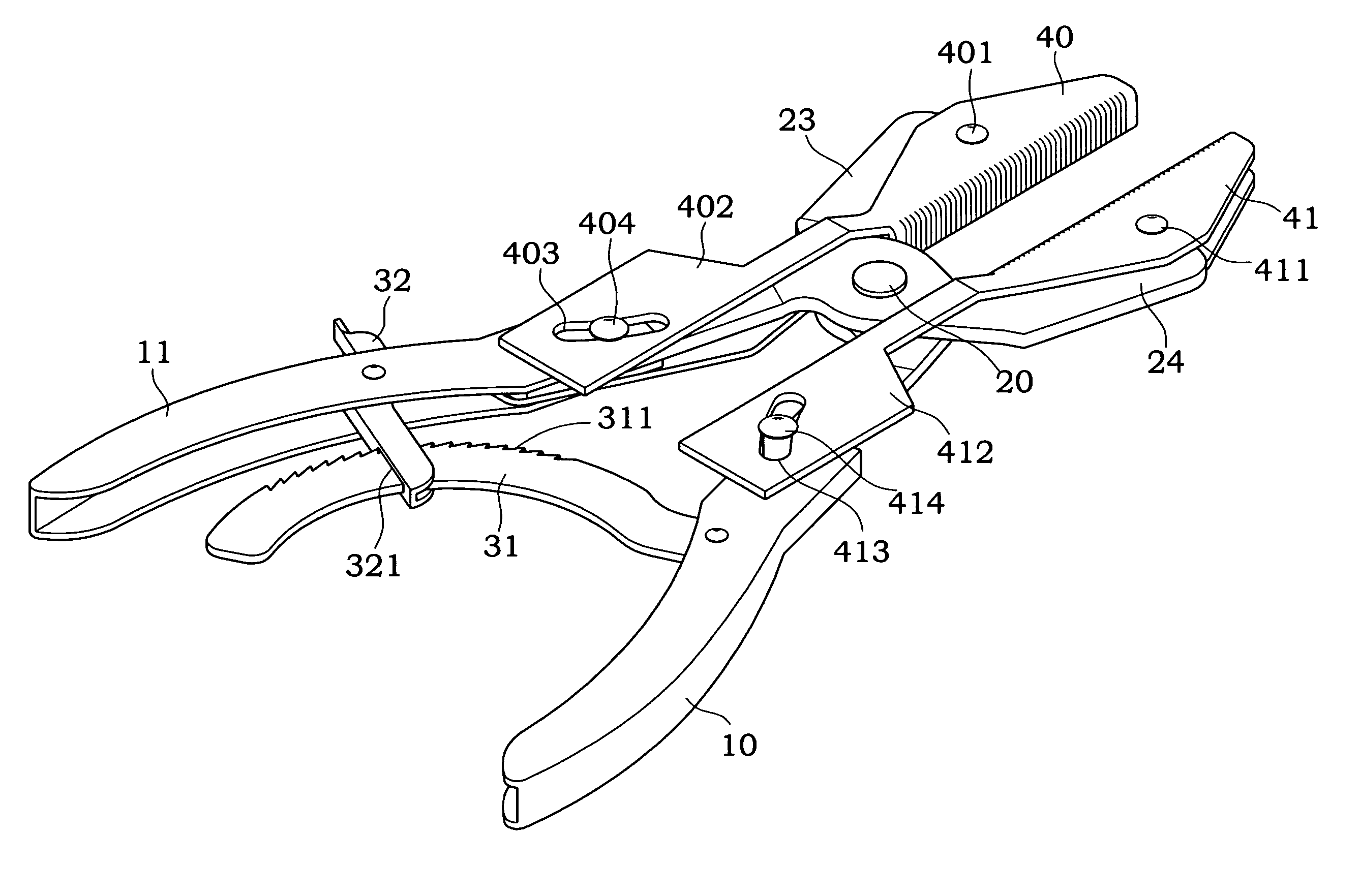
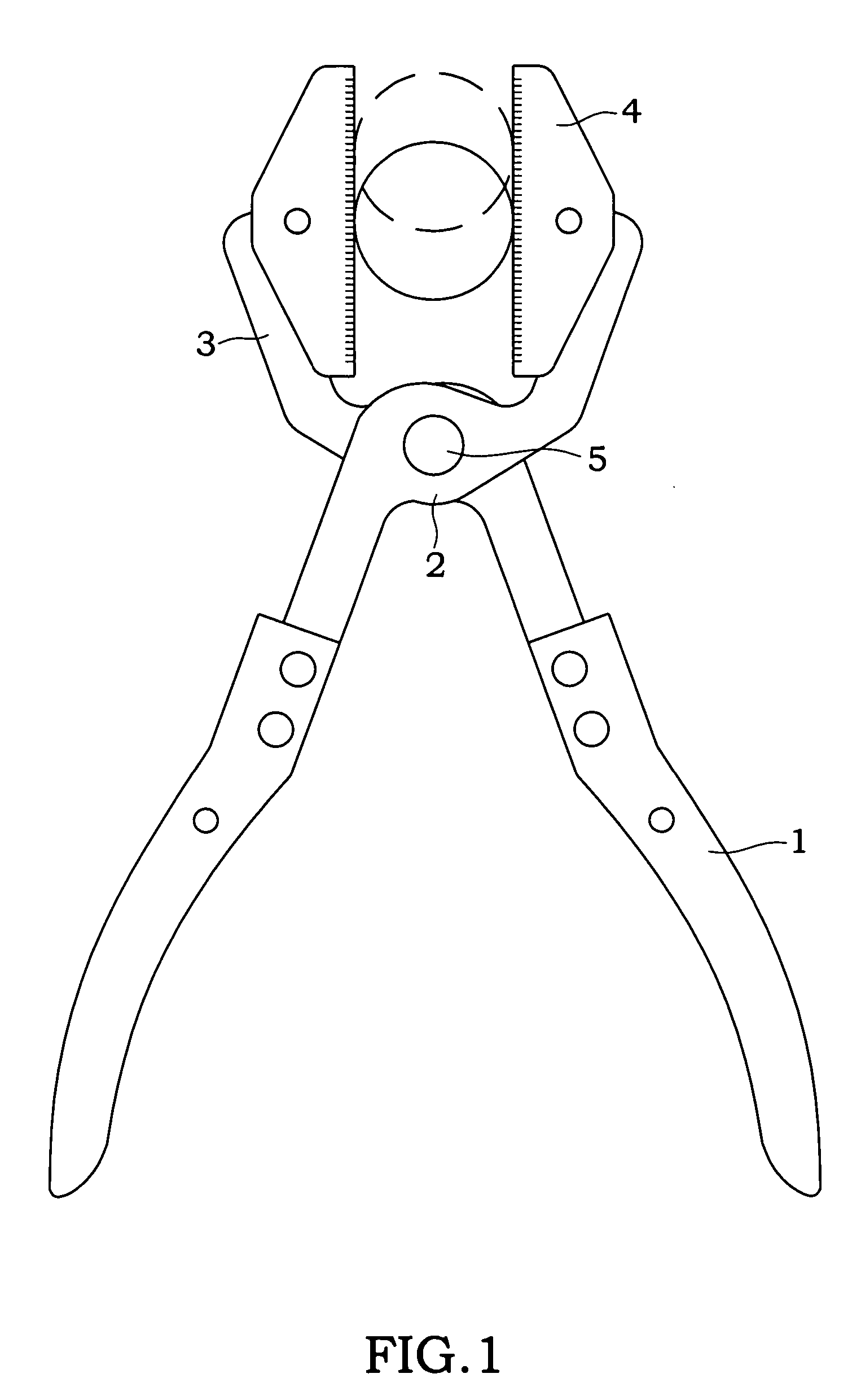
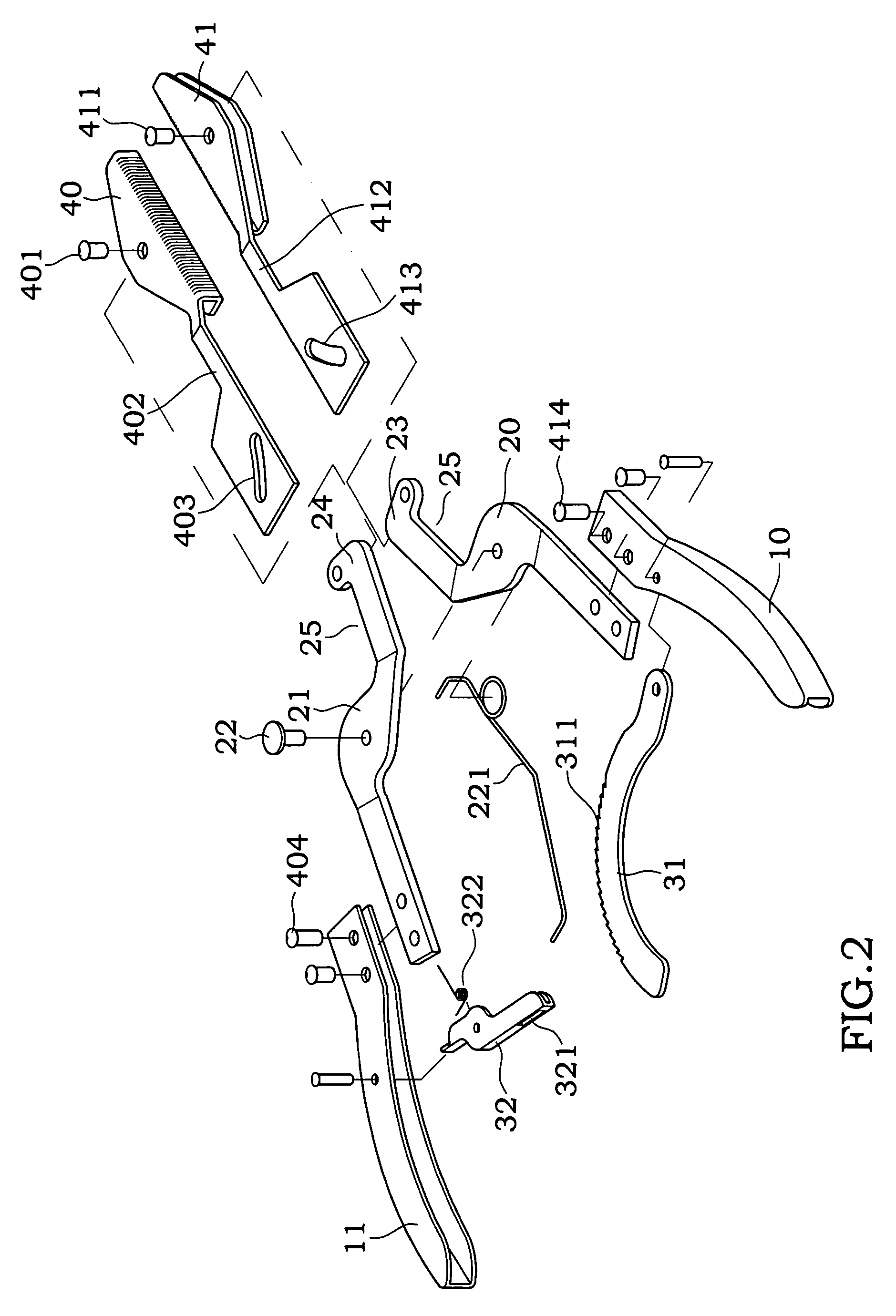
[0019] Referring to FIGS. 2 and 3, an improved pipe wrench assembly is illustrated. The improved pipe wrench assembly comprises:

[0020] a first and a second wrench handles 10, 11, and the first and second wrenches 10, 11 is hollow inside and in an open form on the lateral sides with respect to each other;

[0021] a first and a second wrench heads 20, 21, and their rear sections are of a long plate structure and fixed by a plurality of fixtures onto the front ends of the first and second wrench handles 10, 11, and the head sections of the first and second wrench heads 20, 21 are of a circular plate structure, and the two head sections are stacked with each other and an axle 22 passes through the center of the head sections, and the first wrench head 20 has a resilient member 221, and the rear end of the resilient member 221 is hooked into the second wrench handle 11, such that a user's hand can hold the first and second handles 10, 11 to drive the axle 22 to pivotally rotate about the...


PUM


Abstract

An improved pipe wrench assembly includes a first and a second arms, a first and a second movable wrench members disposed on the front ends of the first and second arms respectively, a guide plate separately extended from the rear ends of the first and second movable wrench members, a sliding groove disposed on the guide plate, and an insert pin pivotally coupled in the sliding groove; wherein another end of the insert pin of the first movable wrench member is fixed to a second handle and another end of the insert pin of the second movable wrench member is fixed to a first handle. With the insert pin and the sliding groove, the first and second movable wrench members can produce a parallel clamping movement when the pipe wrench is clamped and released.

Description

BACKGROUND OF THE INVENTION [0001] 1. Field of the Invention [0002] The present invention relates to a pipe wrench assembly, and more specifically to a pipe wrench having a pair of movable wrench members and a guide plate disposed at a rear end of the movable wrench member, such that the movable wrench members can produce a parallel clamping movement. [0003] 2. Description of the Related Art [0004] In general, conventional wrenches such as vises or micro pliers usually come with a pair of clamping wrench members disposed at the front end of the wrench in a cross aslant fashion. If a user exerts a force on the wrench to clamp a tubular or cylindrical work piece, then the work piece may slip out of the wrench easily, and the tubular or cylindrical work piece cannot be clamped or fixed by such wrench. [0005] In view of the foregoing shortcomings, manufacturers design a pipe wrench assembly to fix a tubular or cylindrical work piece such as a water pipe. Referring to FIG. 1, the pipe wr...

Claims


Application Information

Patent Timeline
Patent Type & Authority Applications(United States)
IPC IPC(8): B25B7/12
CPCB25B7/12B25B7/16B25B7/18
Inventor WANG, CHING-SHU
Owner WANG CHING SHU
Why Eureka
Try Eureka