Paper cutter

a paper cutter and cutter blade technology, applied in the field of paper cutters, can solve the problems of cutting deflection, high and weight that is heavier than desired, and achieve the effects of preventing the deflection of the rotary circular blade, simple structure, and preventing the height of the paper cutter from being high

Inactive Publication Date: 2006-07-27
CARL JIMUKI
View PDF2 Cites 13 Cited by
  • Summary
  • Abstract
  • Description
  • Claims
  • Application Information

AI Technical Summary

Benefits of technology

[0012] An object of the present invention is to provided a paper cutter capable of preventing deflection of a rotary circular blade at a cutting position despite its simple structure, in which height thereof is prevented from being high and weight thereof is reduced.

Problems solved by technology

Thus, height of the paper cutter becomes high and its weight is heavier than desired.
Further, because there is a distance between a position of the rail at the time of cutting and a cutting position by the rotary circular blade, a minute deflection between the slider and the rail in a direction perpendicular to a sliding direction of the slider becomes an enlarged deflection at the cutting position of the rotary circular blade, thereby possibly leading to cutting deflection.

Method used


Image

  • Paper cutter
  • Paper cutter
  • Paper cutter

Examples


embodiments

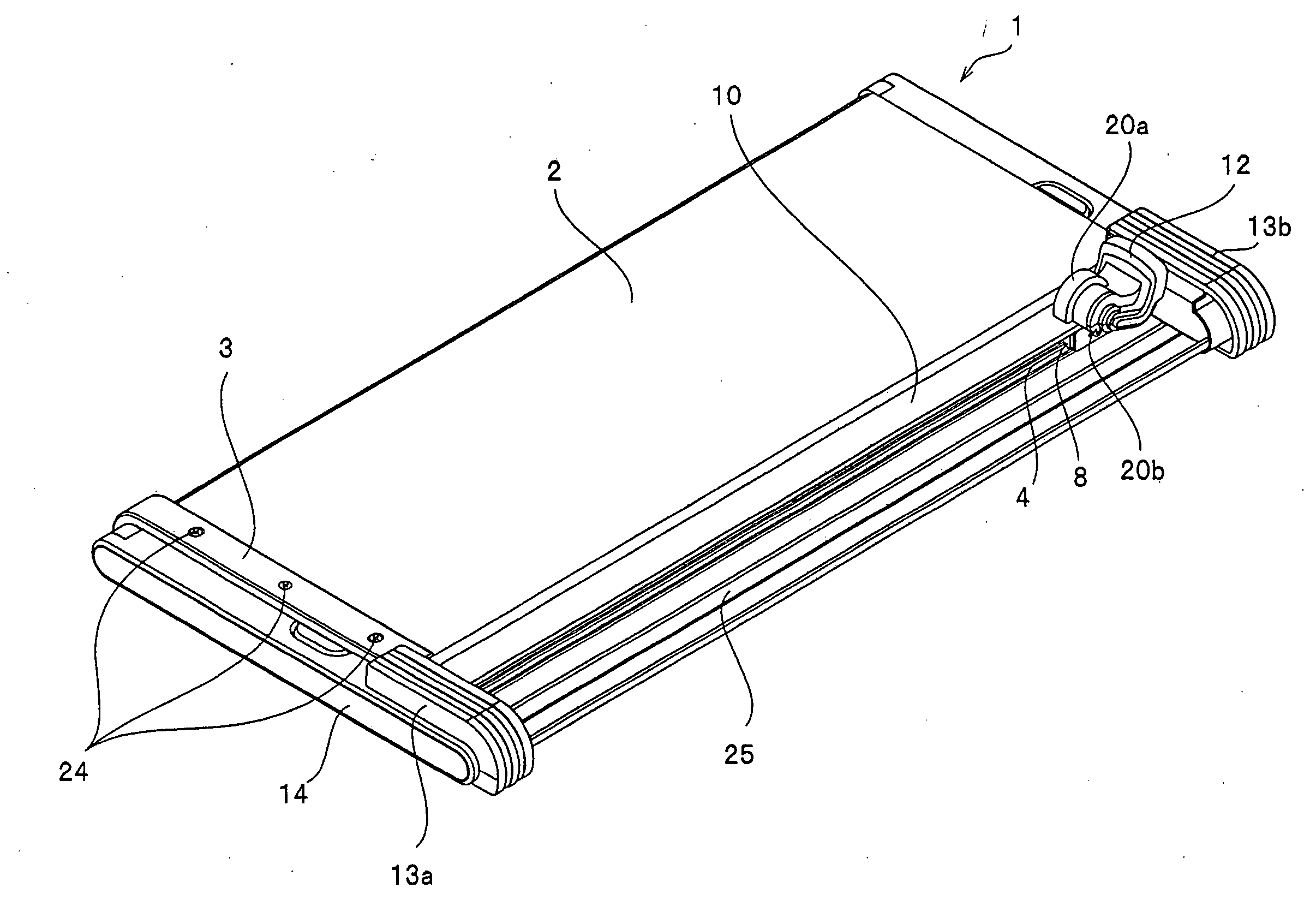
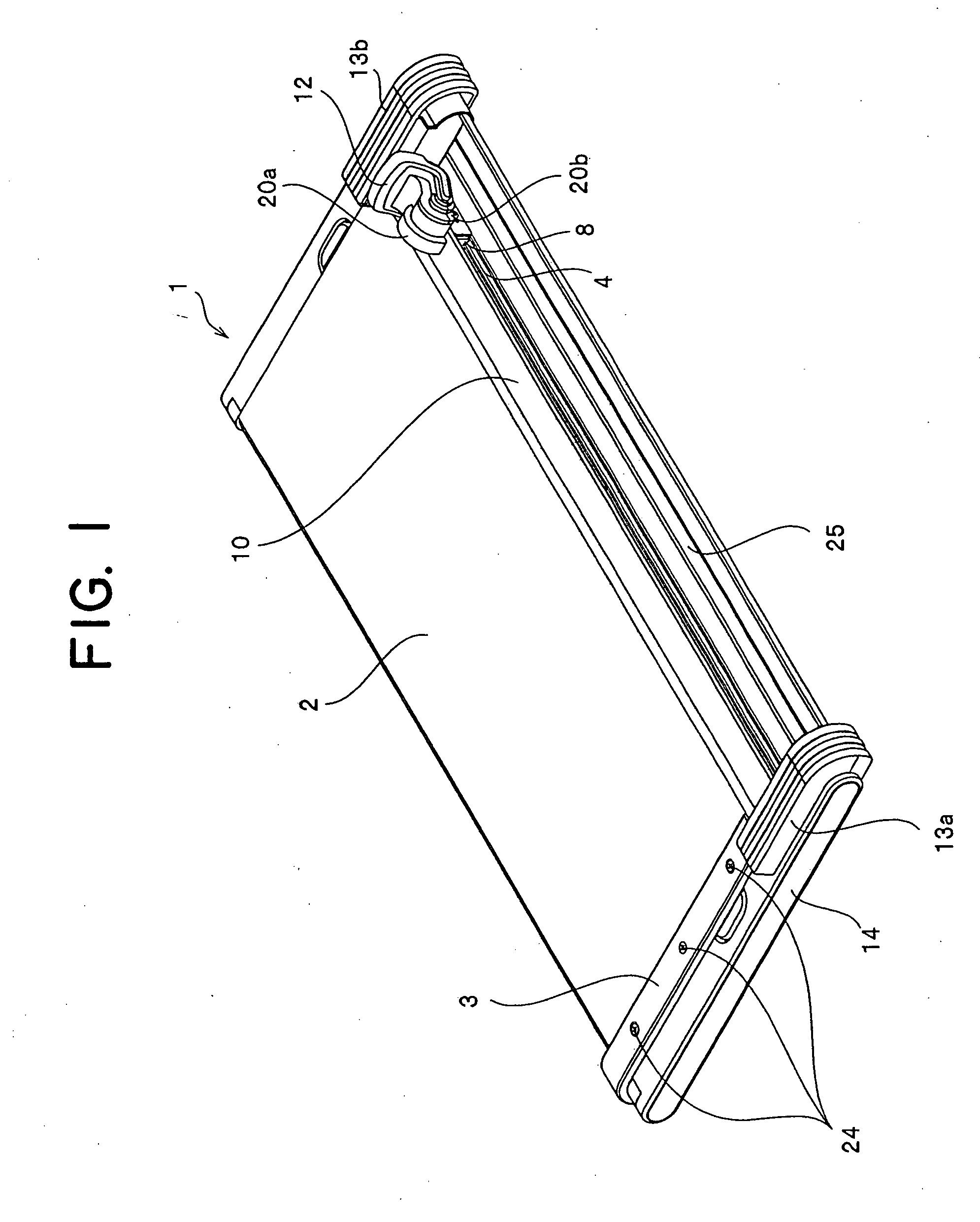
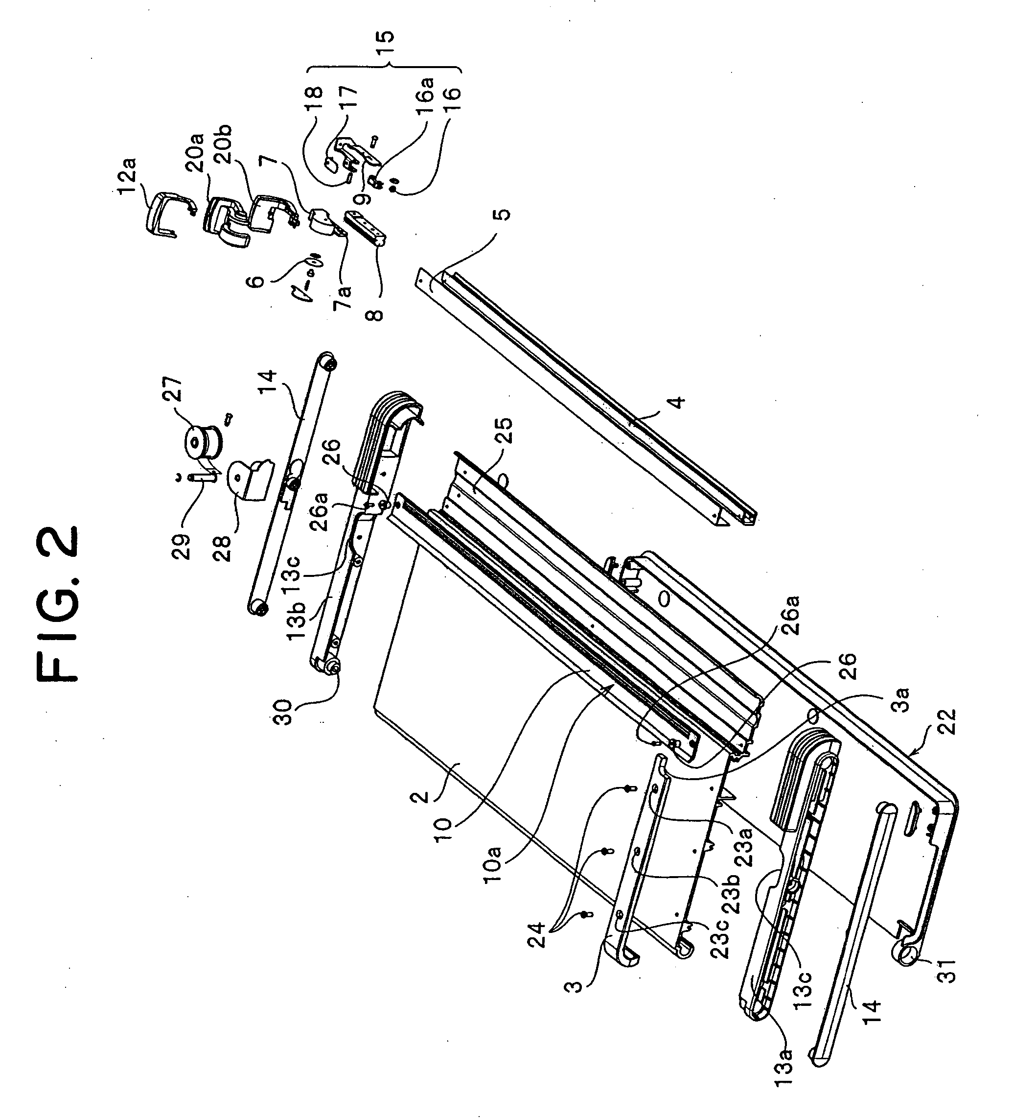
[0051]FIG. 1 shows an entire perspective view of a paper cutter 1 of the present invention, FIG. 2 is an entire structure drawing showing disassembled major components of the paper cutter 1, FIGS. 3 and 4 show a perspective view of the paper cutter 1 with one end portion omitted, and FIGS. 5 to 7 are a perspective view of major portions of the paper pressing plate pressing portion seen from different angles and FIG. 8 is a diagram for explaining expansion operation of an auxiliary paper mounting base.

[0052] As shown in FIG. 1, a long fixed blade 5 is provided at an end portion of a paper mounting base 2 of the paper cutter 1 with its front surface substantially flush with a top surface of the paper mounting base 2, its rear surface being attached with a guide rail 4, and a cutting edge thereof being directed toward the end portion of the paper mounting base 2. A paper pressing plate 10 is disposed on a front surface side of the fixed blade 5. At both ends of the paper pressing plat...


PUM

PropertyMeasurementUnit
transparentaaaaaaaaaa
pressing forceaaaaaaaaaa
timeaaaaaaaaaa

Abstract

The invention provides a paper cutter capable of preventing deflection of the rotary circular blade at a cutting position and height and weight thereof is reduced, wherein a fixed blade is provided at an edge of a paper mounting base and a guide rail is disposed on a rear surface of the fixed blade, a slider is disposed slidably on the guide rail and a rotary blade holder having a rotary circular blade and an arm are attached to the slider, the arm is disposed striding over the fixed blade and a paper pressing plate pressing portion for pressing the paper pressing plate disposed such that it is capable of approaching/separating the fixed blade is attached, the paper pressing plate pressing portion is provided with a roller holder for supporting a pressing roller rotatably, and a position in which the paper pressing plate of the pressing roller is pressed is disposed before a cutting position.

Description

BACKGROUND OF THE INVENTION [0001] 1. Field of the Invention [0002] The present invention relates to a paper cutter for cutting a paper sheet loaded on a paper mounting base by sliding a rotary circular blade along a fixed blade manually. [0003] 2. Description of the Related Art [0004] Conventionally, a paper cutter which cuts a paper sheet mounted on a paper mounting base by sliding a rotary circular blade along a fixed blade by hand has been used. In such a paper cutter, its rotary blade holder rotatably supporting the rotary circular blade is constructed to slide along a guide rail disposed above the paper mounting base. [0005] As a conventionally used paper cutter, there is a paper cutter invented by an applicant of the present invention (see Japanese Patent Application Laid-Open (JP-A) No. 5-245794). FIG. 9 shows an entire perspective view of the paper cutter described in JP-A No. 5-245794. FIG. 10 shows a sectional view taken along a line X-X of FIG. 9. [0006] As shown in FIG....

Claims


Application Information

Patent Timeline
Patent Type & Authority Applications(United States)
IPC IPC(8): B23D19/00B26D1/18
CPCB26D1/205B26D7/015B26D7/025Y10T83/7734Y10T83/8822Y10T83/7763
Inventor SUZUKI, HIDEYUKIKATO, MASAYUKI
Owner CARL JIMUKI
Why Eureka
Try Eureka