Eureka AIR delivers breakthrough ideas for toughest innovation challenges, trusted by R&D personnel around the world.

Filter housing for a drinking water pitcher

a filter housing and drinking water technology, applied in the field of drinking water pitchers, can solve the problems of not being able to only replace the active portion of the sealed cartridge, taking too long for the water to be filtered, and requiring a large amount of tim

Inactive Publication Date: 2006-07-27
TERSANO INC
View PDF18 Cites 27 Cited by
  • Summary
  • Abstract
  • Description
  • Claims
  • Application Information

AI Technical Summary

Benefits of technology

[0009] It is an object of the present invention to obviate or mitigate at least one disadvantage of previous filter housings for drinking water pitchers.
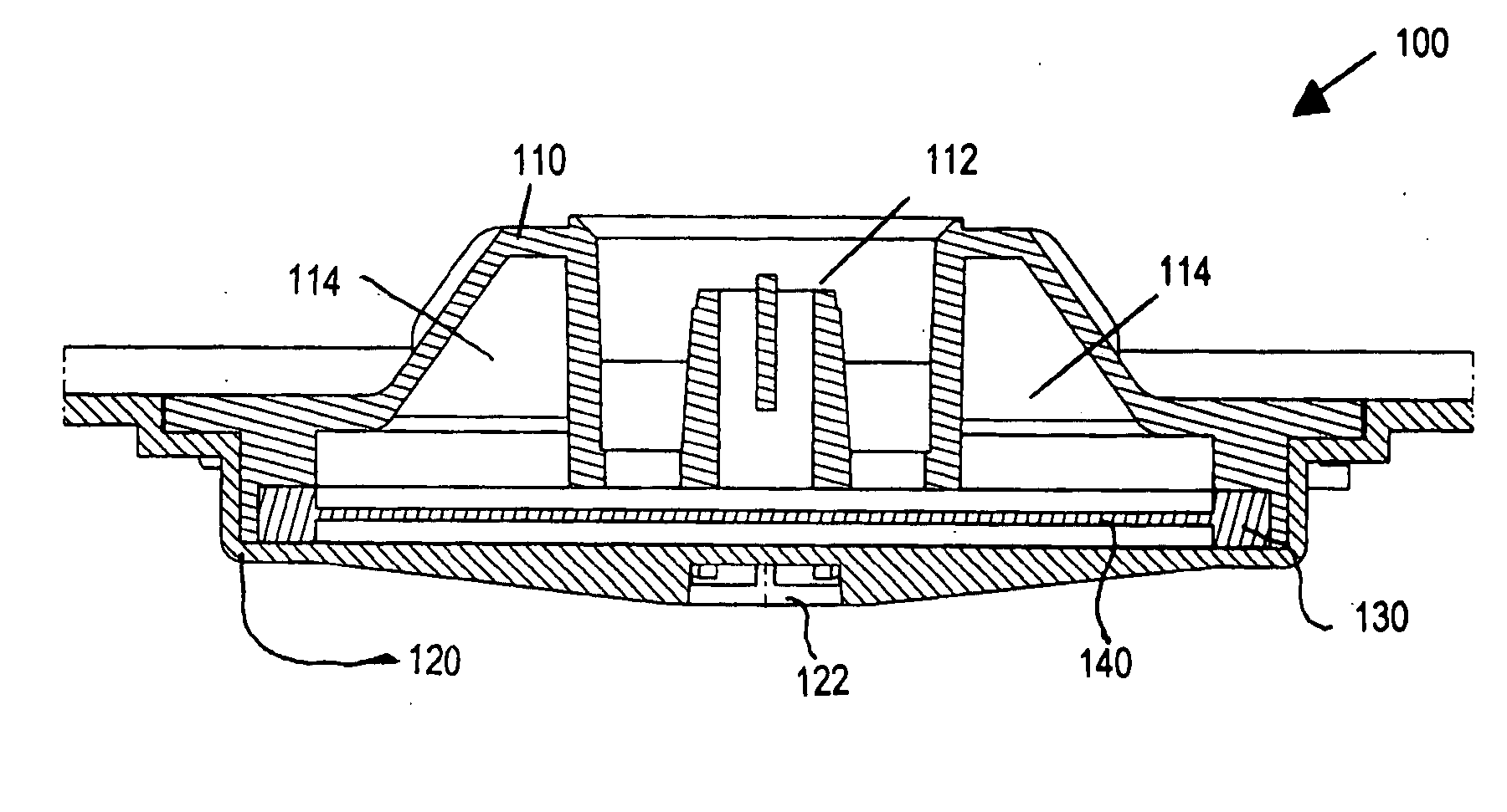
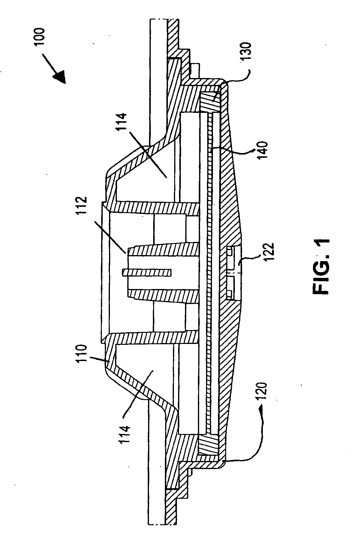
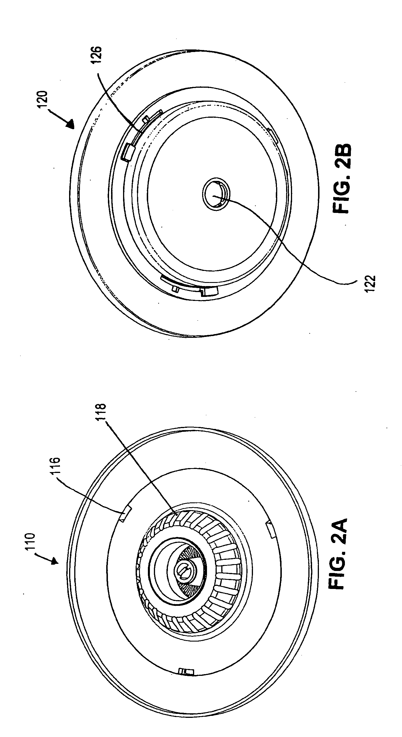
[0010] In an aspect, the present invention provides a filter housing for a drinking water pitcher, including an upper housing portion. The upper housing portion includes a necked down inlet port in an upper surface thereof to increase water flow through rate. The upper housing portion also includes an upper housing chamber to trap air to provide substantially uniform pressure across a lower opening of the upper housing portion. The filter housing further includes a lower housing portion defining an exit port in a lower surface thereof, a volume of the lower housing portion increasing in proximity to the exit port to prevent bottleneck.
[0017] In another aspect, the present invention provides a filter for a drinking water pitcher, the filter including an upper housing portion, a lower housing portion, and a filter media housed in between the upper and lower housing portions. The upper housing portion includes a necked down inlet port in an upper surface thereof to increase water flow through rate, and an upper housing chamber to trap air to provide substantially uniform pressure across the filter media. The lower housing portion defines an exit port in a lower surface thereof. The volume of the lower housing portion increases in proximity to the exit port to create a substantially consistent surface tension across the filter media, and preferably to prevent bottleneck.
[0019] In a further aspect, the present invention provides a filter for a drinking water pitcher, including an upper housing portion. The upper housing portion includes a necked down inlet port in an upper surface thereof to increase water flow through rate. The upper housing portion also includes an upper housing chamber to trap air to provide substantially uniform pressure across a lower opening of the upper housing portion. The filter further includes a lower housing portion including a granulated activated carbon (GAC) filter. The lower housing portion can define an exit port in a lower surface thereof, and a volume of the lower housing portion can increase in proximity to the exit port to prevent bottleneck.
[0020] In a yet further aspect, the present invention provides a drinking water pitcher, including an upper reservoir, a lower reservoir, and a filter provided between the upper reservoir and the lower reservoir such that head pressure from the upper reservoir is applied within the filter. The filter includes an upper housing portion, a lower housing portion, and a removable filter media housed in between the upper and lower housing portions. The upper housing portion includes a necked down inlet port in an upper surface thereof to increase water flow through rate, and an upper housing chamber to trap air to provide substantially uniform pressure across the filter media. The lower housing portion defines an exit port in a lower surface thereof. The volume of the lower housing portion increases in proximity to the exit port to create a substantially consistent surface tension across the filter media.

Problems solved by technology

One of the major complaints from consumers relating to known conventional filter housing and filter media arrangements is that it takes too long for the water to be filtered, such as through the granulated activated carbon (GAC) filters found in a Brita drinking water pitcher.
Nevertheless, the relatively long time it takes for water to be filtered in these pitchers is a deterrent to purchase of such products, as well as to continued use of the products.
There is no way to only replace the active portion of the sealed cartridge, possibly due to potential hazards in GAC handling.

Method used


Image

  • Filter housing for a drinking water pitcher
  • Filter housing for a drinking water pitcher
  • Filter housing for a drinking water pitcher

Examples


Embodiment Construction

[0035] Generally, the present invention provides a filter housing for a drinking water pitcher. The filter housing includes an upper housing portion and a lower housing portion. A filter media can be housed in between the upper and lower housing portions. The upper and lower housing portions co-operate to provide increased water flow through rate. The filter housing includes a necked down inlet port. Chambers in the upper housing are filled with air. An angle of the lower housing preferably extends to the exit port to create a consistent surface tension across the entire surface of the filter media. The filter housing is preferably placed between an upper reservoir and a lower reservoir of the drinking water pitcher, and can be removably attached to, or seated within, the lower reservoir.

[0036]FIG. 1 is a close up section view showing geometric features of a filter housing according to an embodiment of the present invention. The filter housing shown in FIG. 1 includes a filter, tho...


PUM

PropertyMeasurementUnit
Angleaaaaaaaaaa
Diameteraaaaaaaaaa
Diameteraaaaaaaaaa

Abstract

A filter housing for a drinking water pitcher is provided. The filter housing includes an upper housing portion and a lower housing portion. A filter media can be housed in between the upper and lower housing portions. The upper and lower housing portions co-operate to provide increased water flow through rate. The filter housing includes a necked down inlet port. Chambers in the upper housing are filled with air. Preferably, an angle of the lower housing preferably extends to the exit port to create a consistent surface tension across the entire surface of the filter media. The filter housing is preferably placed between an upper reservoir and a lower reservoir of the drinking water pitcher, and can be removably attached to, or seated within, the lower reservoir.

Description

CROSS-REFERENCE TO RELATED APPLICATIONS [0001] This application claims the benefit of priority of U.S. Provisional Patent Application Ser. No. 60 / 645,073, filed Jan. 21, 2005, which is incorporated herein by reference.FIELD OF THE INVENTION [0002] The present invention relates generally to drinking water pitchers. More particularly, the present invention relates to a filter housing for a drinking water pitcher. BACKGROUND OF THE INVENTION [0003] Increased concern from the public on issues of water quality has resulted in an explosion of water filtration devices on the market, particularly for household use. A popular household water filtration device is in the style of a pour-through pitcher. Typically, unfiltered water is added to a basin at the top of the device. Through the action of gravity, water percolates through a filtering media (usually consisting of granulated activated carbon) located between the basin and a collection reservoir. Filtered water is then dispensed from the...

Claims


Application Information

Patent Timeline
IPC IPC(8): B01D24/00
CPCC02F1/003C02F1/281C02F2307/04
Inventor HENGSPERGER, STEVE L.NAMESPETRA, JUSTIN L.CALDWELL, CHRISTOPHER B.ZULIK, RICHARD S.
Owner TERSANO INC
Why Eureka
Eureka Blog
Learn More