Oblique projection optical system

a projection optical system and optical system technology, applied in the field of projection optical systems, can solve the problems of reducing the size of the rear projection apparatus in terms of aberration correction, increasing the cost of the entire optical system, and achieving the effect of favorable optical performan

Inactive Publication Date: 2006-07-27
KONICA MINOLTA OPTO
View PDF16 Cites 32 Cited by
  • Summary
  • Abstract
  • Description
  • Claims
  • Application Information

AI Technical Summary

Benefits of technology

[0010] In view of the conditions described above, the present invention has been made, and it is an object of the invention to provide an oblique projection optical system which pr

Problems solved by technology

However, just use of a reflective optical element having a positive optical power and a reflective optical element having a negative optical element, as described in patent documents 1 to 3, suffers from limitations in achieving the slimming-down of a rear projection apparatus in terms of correction of aberration such as curvature of

Method used


Image

  • Oblique projection optical system
  • Oblique projection optical system
  • Oblique projection optical system

Examples


examples

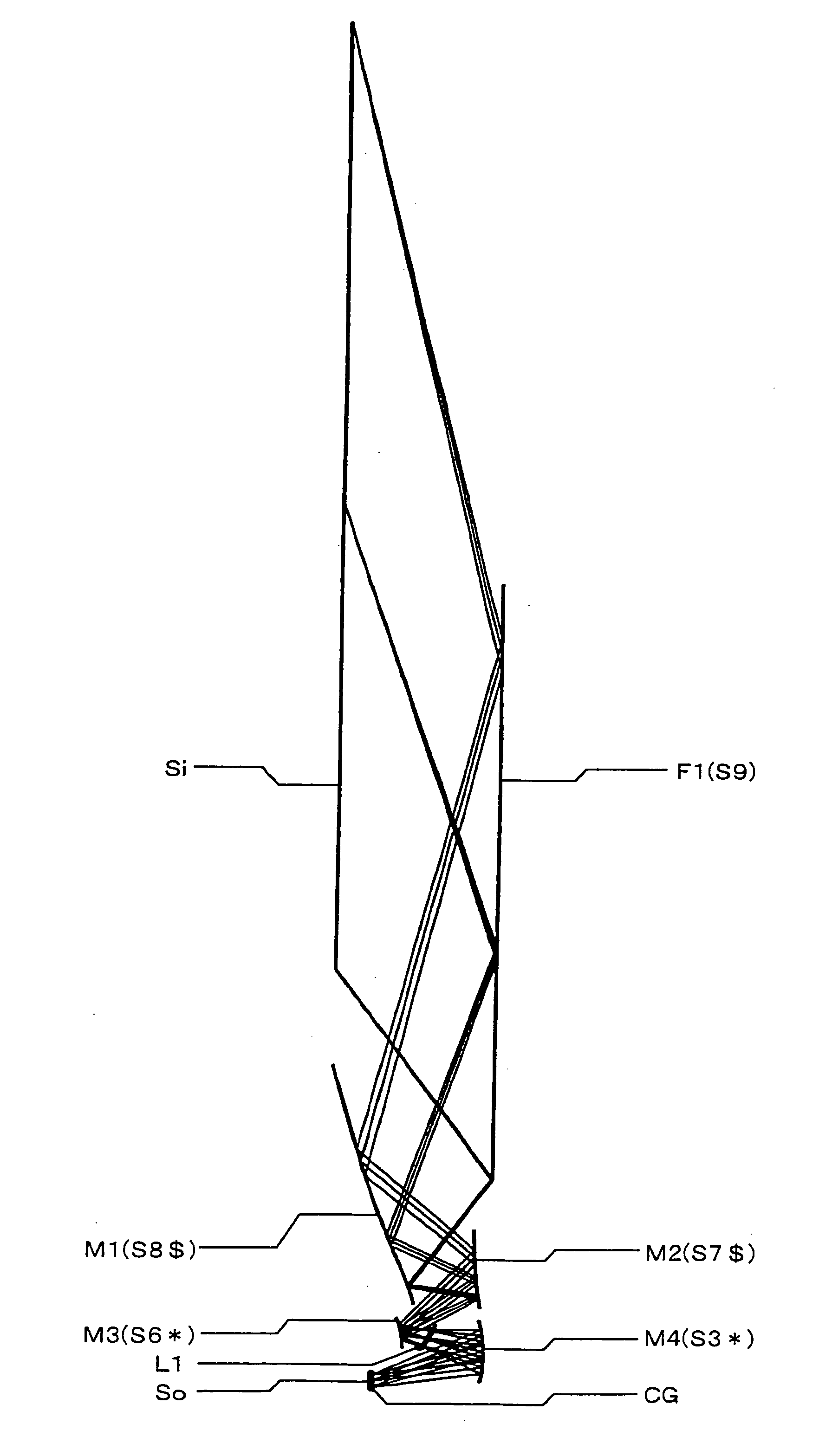
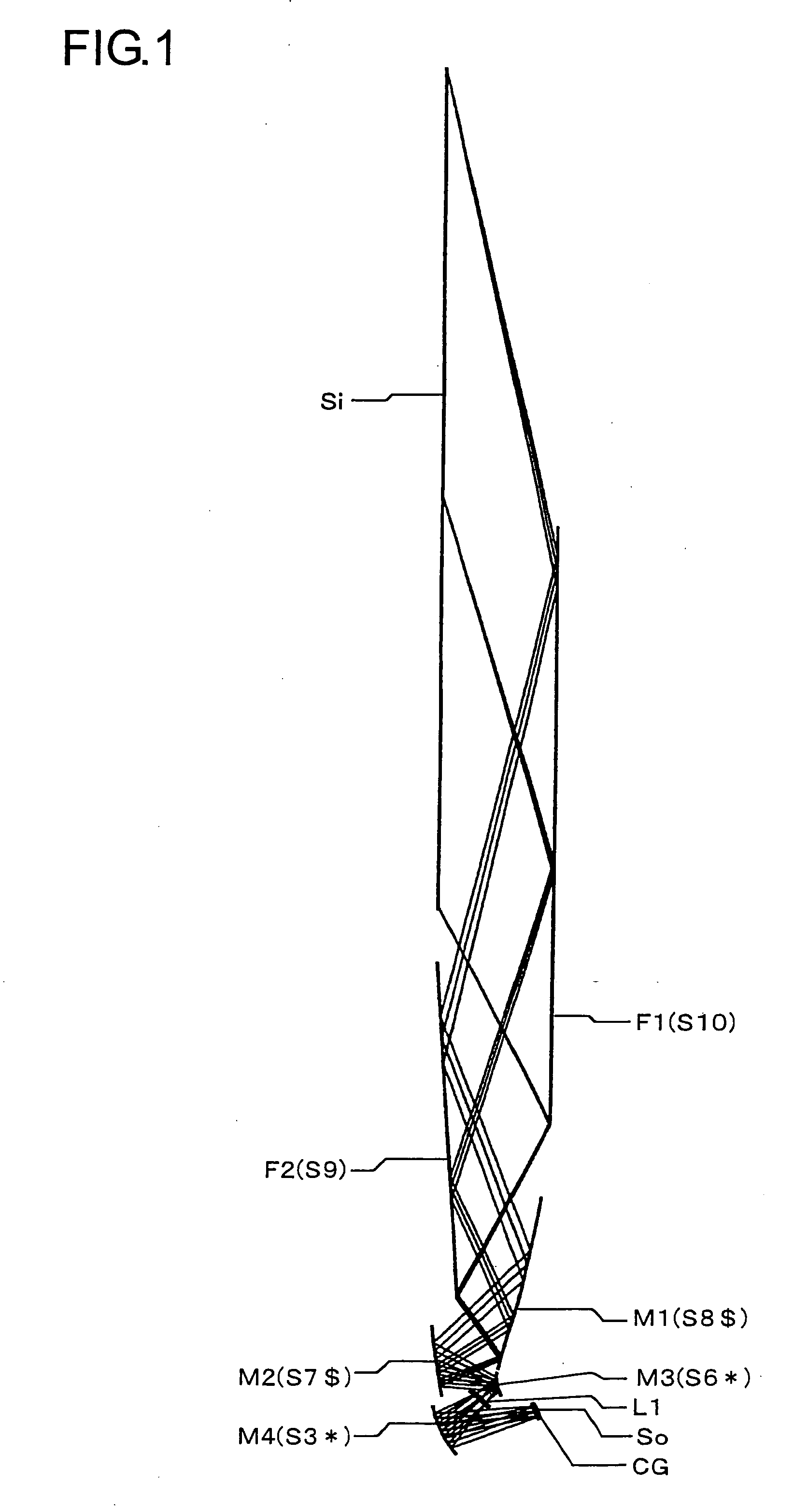
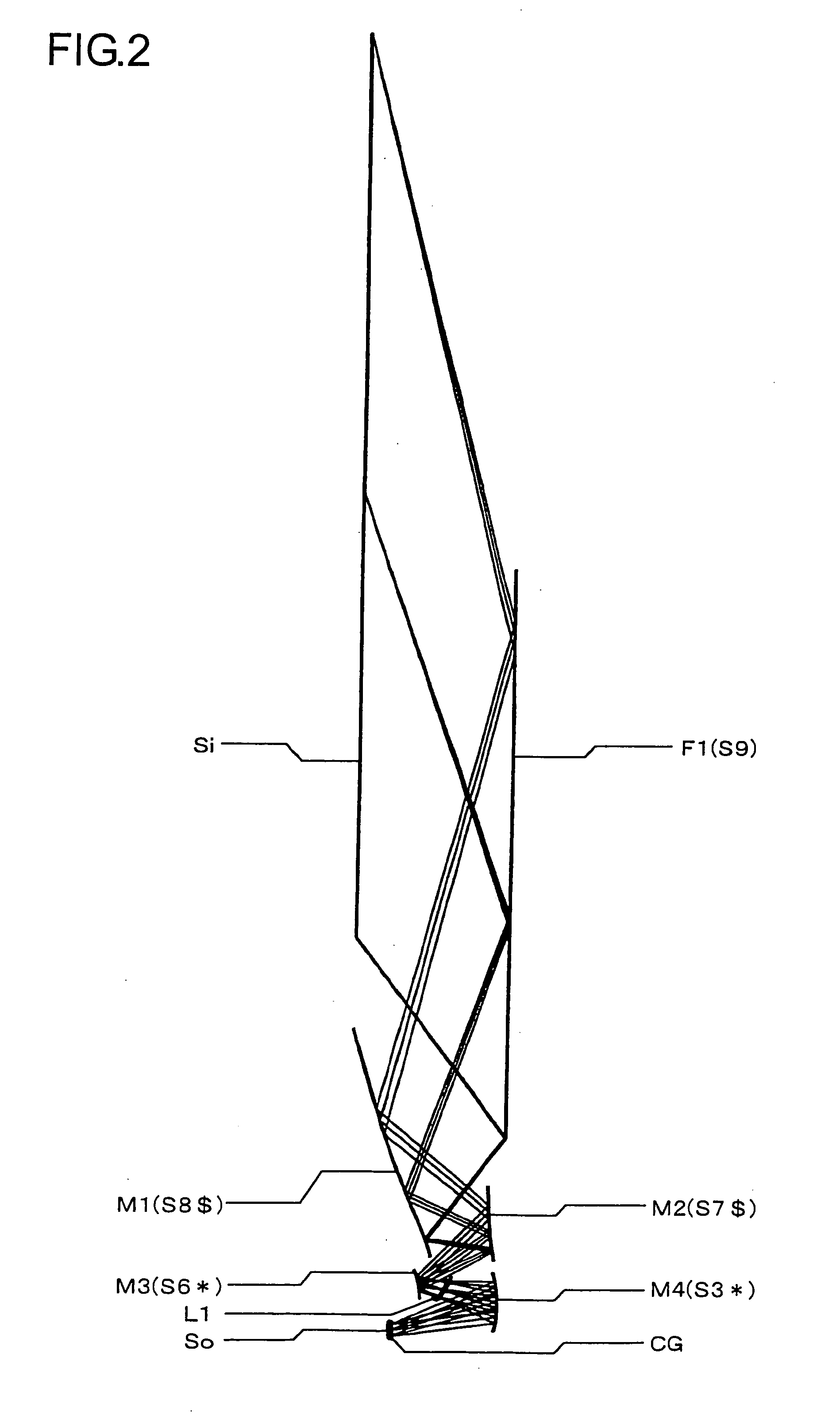
[0111] Hereinafter, practical examples of the oblique projection optical system embodying the present invention will be presented with reference to their construction data and the like. Examples 1 to 7 presented below are numerical examples of oblique projection optical systems corresponding to the first to seventh embodiments, respectively, described previously. Thus, the optical construction diagrams (FIGS. 1 to 14, FIG. 35) showing the first to seventh embodiments also show the optical arrangement, projection optical path, and other features of Examples 1 to 7, respectively. The construction data of each example shows the optical arrangement through the entire system starting with the primary image surface So on the reduction side (corresponding to the image formation surface of the display device, i.e., object surface, in enlargement projection) to the secondary image surface Si on the enlargement side (corresponding to the screen surface, i.e., image surface, in enlargement pro...


PUM


Abstract

In an oblique projection optical system for performing enlargement projection from a primary image surface on the reduction side to a secondary image surface on the enlargement side, at least one reflective surface having an optical power is provided, and, assuming that of the aforementioned surfaces, the reflective surface located on the most secondary image surface side in the optical path is a first curved reflective surface, the first curved reflective surface has a portion having a positive optical power and a portion having a negative optical power.

Description

[0001] This application is based on Japanese Patent Application No. 2004-325954 filed on Nov. 10, 2004, the contents of which are hereby incorporated by reference. BACKGROUND OF THE INVENTION [0002] 1. Field of the Invention [0003] The present invention relates to a projection optical system, and more specifically, to an oblique projection optical system that has a reflective optical element with an optical construction suitable for rear projection and that performs enlargement projection in an oblique direction from a primary image surface to a secondary image surface. [0004] 2. Description of Related Art [0005] Examples of an oblique optical system employing a reflective optical element for wide-angle enlargement projection from the primary image surface on the reduction side to the secondary image surface on the enlargement side include those proposed in patent documents 1 to 3. The oblique projection optical systems as described in patent documents 1 to 3 employs a reflective op...

Claims


Application Information

Patent Timeline
IPC IPC(8): G03B21/22G03B21/28
CPCG02B17/0848G03B21/10G03B21/28
Inventor KUWA, TOMIEI
Owner KONICA MINOLTA OPTO
Why Eureka
Try Eureka