Image forming apparatus

a technology of image forming apparatus and forming tube, which is applied in the direction of electrographic process apparatus, instruments, optics, etc., can solve the problems of low sensor output, difficult to perform precise detection of patch density, and inability to keep the initial surface condition, so as to prevent density loss

Active Publication Date: 2006-07-27
KYOCERA DOCUMENT SOLUTIONS INC
View PDF0 Cites 15 Cited by
  • Summary
  • Abstract
  • Description
  • Claims
  • Application Information

AI Technical Summary

Benefits of technology

[0045] With this design, by using as the transfer belt or the intermediary transfer belt an elastic belt, it is possible to precisely measure the amount of toner adhered, and it is ...

Problems solved by technology

Here, if the toner carrying member has a low-gloss surface, regardless of the patch density, the sensor output is low, making it difficult to perform precise detection of the patch density.
This makes it impossible to keep the initial surface condition until the expiration of the warranted normal-operation period of the toner carrying member.
Thus, according to the methods disclosed in patent publications 1 and 2, it is difficult to precisely measure the amount of toner adhered.
As described earlier, however, it is difficult to maintain the initial surface condition until the ex...

Method used


Image

  • Image forming apparatus
  • Image forming apparatus
  • Image forming apparatus

Examples


Embodiment Construction

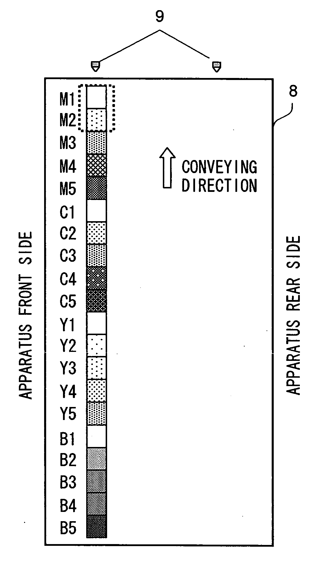
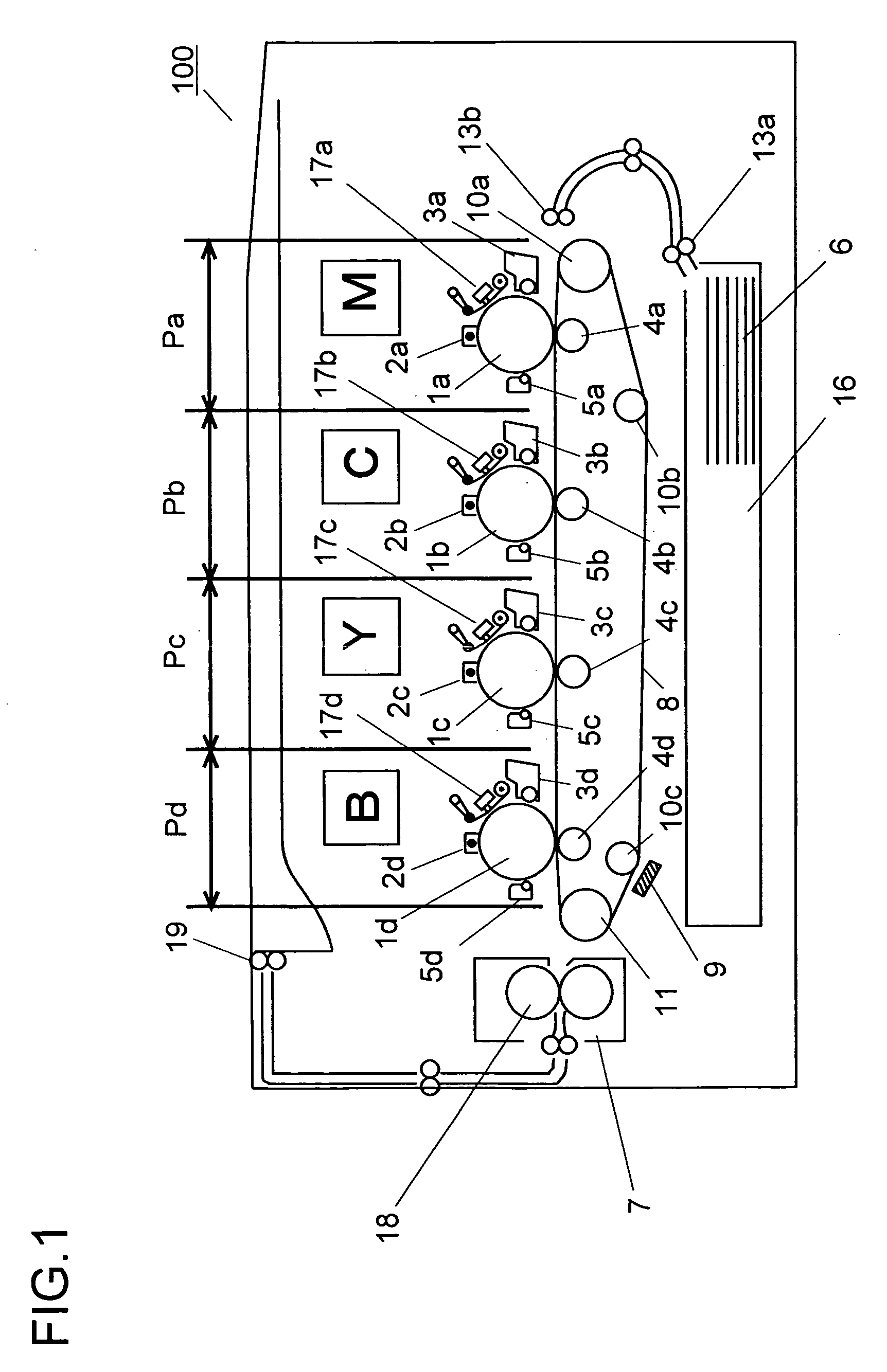
[0052] Hereinafter, with reference to the drawings, an embodiment of the present invention will be described in detail. FIG. 1 is a diagram schematically showing an image forming apparatus according to the present invention. Here, a tandem-type color image forming apparatus will be dealt with. Inside the body of the image forming apparatus 100, four image forming sections Pa, Pb, Pc, and Pd are arranged in this order from the upstream side (the right side in FIG. 1) of a transfer belt 8. These image forming sections Pa, Pb, Pc, and Pd are for forming images of four different colors (magenta, cyan, yellow, and black), and form a magenta, a cyan, a yellow, and a black image sequentially, each through an image forming process involving charging, exposure, development, and transfer.

[0053] In the image forming sections Pa, Pb, Pc, and Pd, photoconductive drums 1a, 1b, 1c, and 1d are arranged that carry visible images (toner images) of the different colors. The toner images formed on the...


PUM


Abstract

The difference between the light reception output signals representing the amounts of regularly and irregularly reflected light as measured, with optical detecting means that can measure the amount of regularly and irregularly reflected light simultaneously, when no toner is adhered to a transfer belt is set as a reference value, a corrected output value is calculated by correcting, based on the reference value, the difference between the light reception output signals representing the amounts of regularly and irregularly reflected light as measured when a toner image is formed, and the amount of toner adhered to the transfer belt is calculated based on the corrected output value. With transfer belts of different colors, if their surface gloss is equal to or lower than a predetermined value, the relationship between the coverage ratio and the toner adhesion amount remains approximately identical. Thus, when a transfer belt whose initial surface gloss is equal to or lower than 20 at a measurement angle of 60 degrees, the amount of toner adhered can be measured precisely until the expiration of the warranted use period of the belt.

Description

[0001] This application is based on Japanese Patent Application No. 2005-014285 filed on Jan. 21, 2005, the contents of which are hereby incorporated by reference. BACKGROUND OF THE INVENTION [0002] 1. Field of the Invention [0003] The present invention relates to an image forming apparatus relying on electrophotography, and more particularly to how to measure the amount of toner adhered to a toner carrying member that carries it. [0004] 2. Description of Related Art [0005] In an image forming apparatus employing an electrophotographic process, density correction and color-shift correction are generally achieved by transferring toner directly onto a toner carrying member to form a patch image (reference image) thereon and then detecting the amount of toner with which and the position at which the patch image is formed. For example, in a tandem-type full-color image forming apparatus, patch images of different colors are formed on a transfer belt by a cyan, a magenta, a yellow, and a...

Claims


Application Information

Patent Timeline
IPC IPC(8): G03G15/00
CPCG03G2215/00059G03G15/5058
Inventor MATAYOSHI, AKIRAHASHIMOTO, MITSUHIRO
Owner KYOCERA DOCUMENT SOLUTIONS INC
Why Eureka
Try Eureka