Printer with a peeler mechanism

a peeler and printing machine technology, applied in the field of peeler mechanism, can solve the problems of inconvenient operation, undesirable opening/closing cover, and printer size and cost increase, and achieve the effect of convenient opening

Inactive Publication Date: 2006-07-27
SEIKO EPSON CORP
View PDF5 Cites 37 Cited by
  • Summary
  • Abstract
  • Description
  • Claims
  • Application Information

AI Technical Summary

Benefits of technology

[0015] The first lock member in this aspect of the invention moves linearly between positions for locking and releasing (unlocking) the opening / closing cover. The opening / closing cover can thus be held in the locked position with more strength than when the first lock member swings forward and back in an arc to lock and unlock the opening / closing cover. When the cover is locked by an engagement pin fitting into an engagement channel, the depth of engagement is greater when the members slide together in a straight line than when the members are engaged along a curved path. The members thus lock together more firmly and are not unlocked by external vibration and impact.
[0019] When thus comprised the peeler unit cannot be locked in the closed position if only the peeler unit is closed. This prevents forgetting to close the opening / closing cover. Furthermore, a single sensor for detecting if the peeler unit is locked in the closed position can be used to detect the open or closed state of both the opening / closing cover and peeler unit.
[0021] When the manual operating member of the printer with a peeler mechanism according to the present invention is operated, the first lock member that locks the opening / closing cover that closes the roll paper compartment moves in a straight line to unlock and thus release the opening / closing cover. At the same time this first lock member pushes against a second lock member that locks the peeler unit closed, and thus unlocks the second lock member. Continued operation of the manual operating member after the opening / closing cover is unlocked causes the first lock member to pivot and push the opening / closing cover up and open. Unlocking and opening the opening / closing cover can thus be completed in a single continuous action.
[0022] A single continuous operation of the manual operating member can thus unlock both the opening / closing cover and peeler unit, and can push the opening / closing cover up and open. The opening / closing cover and peeler unit can thus be easily opened.
[0023] Furthermore, because the first lock member pushes the second lock member and unlocks the peeler unit, a separate mechanism for unlocking the peeler unit is not needed, and a compact unlocking mechanism for the opening / closing cover and peeler unit can be provided.
[0024] Yet further, because the first lock member for locking the opening / closing cover moves linearly between the locked and unlocked positions, the locked position can be held with greater strength than in a conventional arrangement in which the lock member swings in an arc between the locked and unlocked positions. Therefore, while the mechanism of the present invention enables the operations of unlocking the opening / closing cover and pushing the opening / closing cover up and open to be simply completed in a single continuous action, the opening / closing cover is also prevented from being accidentally opened by external shocks or vibrations.

Problems solved by technology

The opening / closing cover thus cannot be opened by a single operation, and operation is tedious and inconvenient.
However, if these mechanisms are thus linked and the lock mechanism is accidentally released by impact or vibration, the opening / closing cover will undesirably open.
This is particularly a problem if the cover thus opens during printing because printing cannot proceed.
Furthermore, printer size and cost increase undesirably because these mechanism are not compact.
Yet further, if the opening and closing operations are not simple, printer operability also decreases undesirably.

Method used


Image

  • Printer with a peeler mechanism
  • Printer with a peeler mechanism
  • Printer with a peeler mechanism

Examples


Embodiment Construction

[0040] A printer with a peeler mechanism according to a preferred embodiment of the present invention is described below with reference to the accompanying figures.

[0041] General Configuration

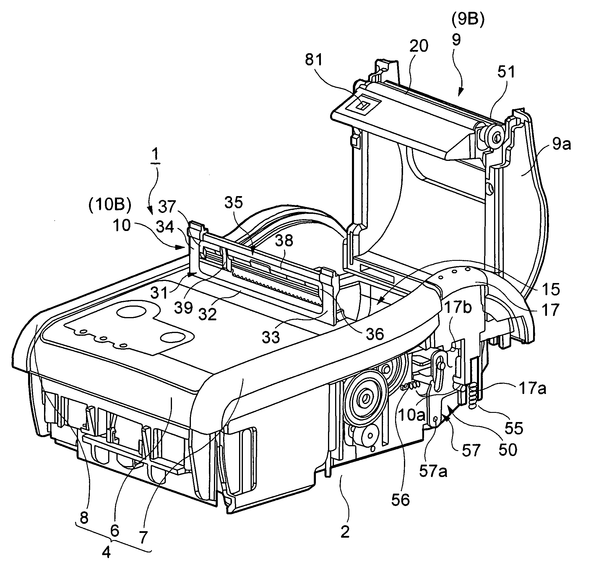
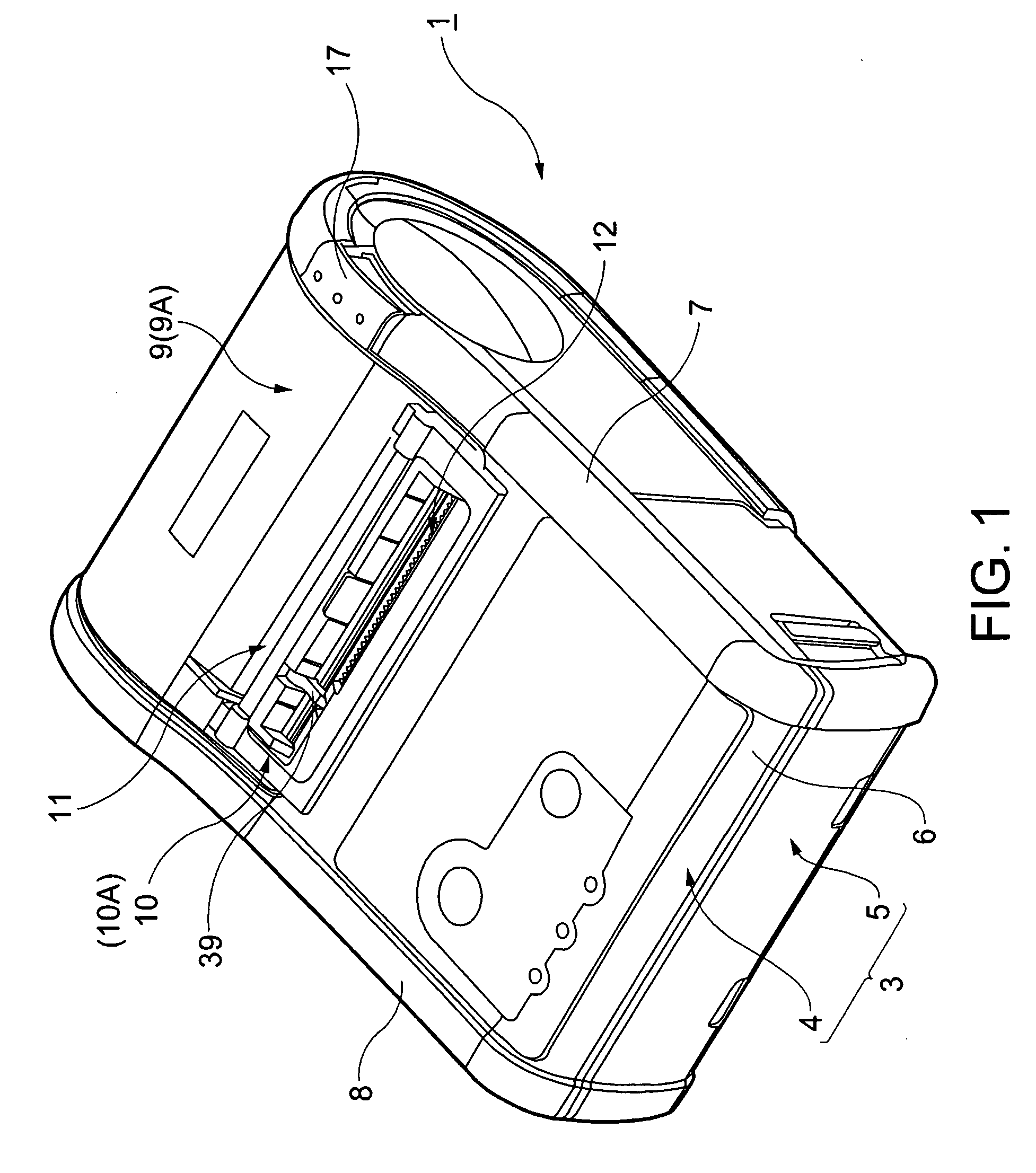
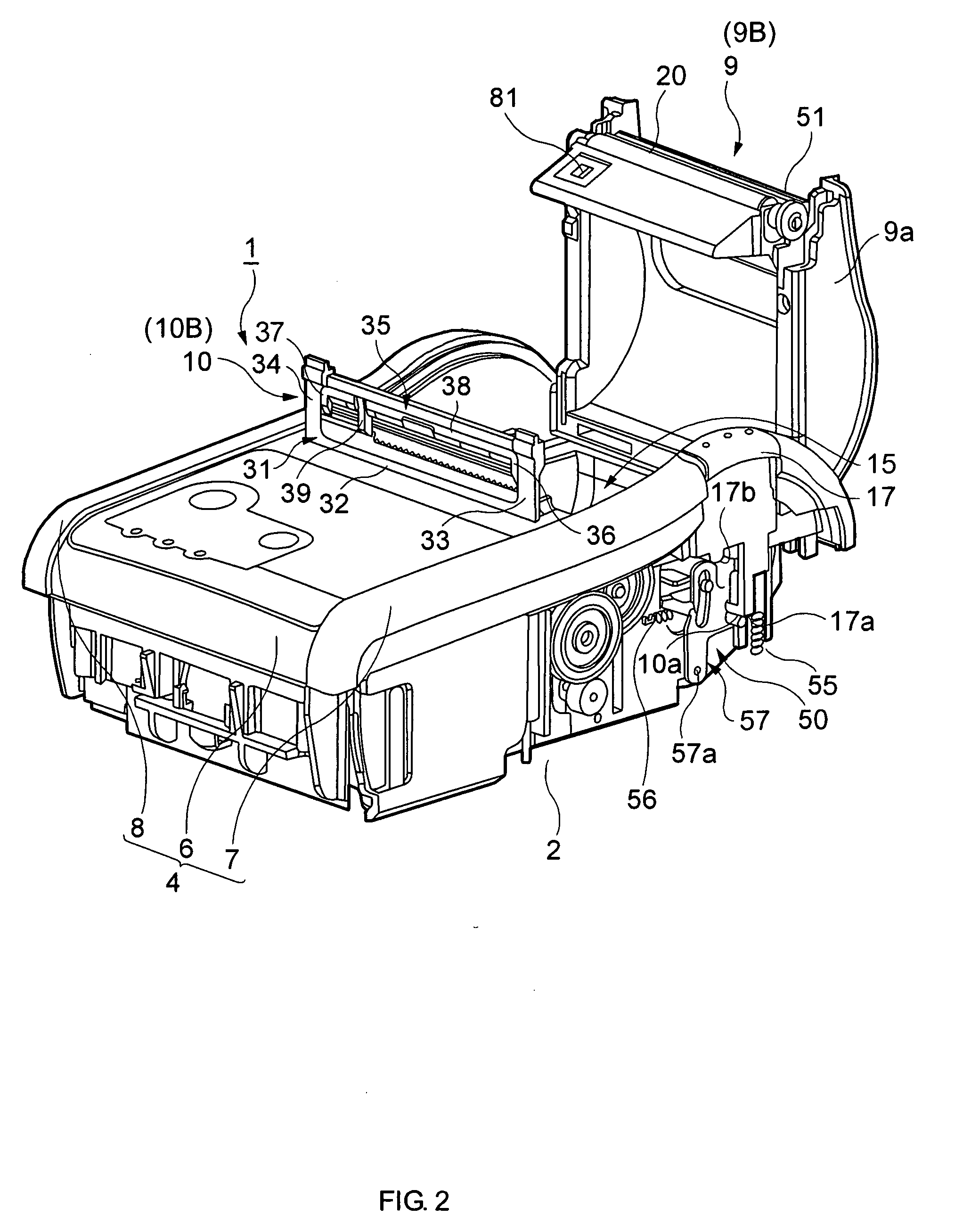
[0042] A printer with a peeler mechanism 1 according to this embodiment of the invention has a relatively flat, box-like shape, preferably in a rectangular configuration, as shown in FIG. 1 that is longer from front to back than across the width. The printer is composed of a printer body 2 (defining a printer mechanism, see FIG. 2) and a printer case 3 covering the printer body 2.

[0043] The printer case 3 is composed of a top portion 4 and a bottom portion 5. FIG. 2 shows the printer with a peeler mechanism 1 with the bottom portion 5 removed. The top portion 4 of the printer body 2 is composed of a top front case portion 6 that covers the front top part of the printer, and right and left side case portions 7 and 8. An opening / closing cover 9 that opens and closes is disposed at the top rear...


PUM


Abstract

A printer having an opening / closing cover for providing access to a roll paper compartment, a peeler mechanism for peeling printed labels from a web and for dispensing the peeled printed labels from the printer and an opening and closing mechanism 50 which locks and unlocks the cover and a peeler unit 10 of the peeler mechanism in response to the manual operation of a manual operating member such as a release button 17 with a single easy operation. When the release button 17 is depressed into a first operating position 17B, a lock lever 52 of the opening / closing mechanism 50 slides from a locked position 52A to a released position 52B to disengage the lock lever 52 thus unlocking the opening / closing cover 9. At the same time, the sliding lock lever 52 pushes engaging claws 74a, 73a that lock or unlocks the peeler unit 10. When the cover release button 17 is further depressed into a second operating position 17C, the lock lever 52 swings and a cover-lifting surface 54 on the lock lever 52 pushes the opening / closing cover 9 up causing the unlocked opening / closing cover 9 to move into a raised open position. Simply pushing the cover release button 17 thus unlocks and raises the opening / closing cover 9, and unlocks the peeler unit 10.

Description

BACKGROUND OF THE INVENTION [0001] 1. Field of the Invention [0002] The present invention relates to a peeler mechanism for peeling printed labels from a web, and relates more particularly to a printer having a peeler mechanism for dispensing printed labels. More particularly, the present invention is a printer having a peeler mechanism composed of an opening / closing cover that can be opened and closed to load roll paper having label paper wound in a roll into a roll paper compartment, and a peeler unit that can be opened and closed to open and close the web discharge path of the peeler mechanism, and relates specifically to an opening / closing mechanism for locking the opening / closing cover and peeler unit in a closed position to the printer and releasing the opening / closing cover and peeler unit from this closed and locked position. [0003] 2. Description of Related Art [0004] Some printers that print to roll paper delivered from paper wound in a roll have a paper feed roller for co...

Claims


Application Information

Patent Timeline
Patent Type & Authority Applications(United States)
IPC IPC(8): B41J15/02
CPCB41J3/4075Y10T292/0848Y10T292/0951Y10T292/1043Y10T292/1084
Inventor KAWAKAMI, HIDEKIYAMADA, MASAHIKO
Owner SEIKO EPSON CORP
Why Eureka
Try Eureka