Scroll casing for centrifugal blowers

a centrifugal blower and casing technology, applied in the direction of machines/engines, stators, liquid fuel engines, etc., can solve the problems of centrifugal blowers, abnormal flow, and reduction of efficiency by 50% or more in comparison

Inactive Publication Date: 2006-07-27
IND UNIV COOP FOUND SUNMOON UNIV +1
View PDF11 Cites 15 Cited by
  • Summary
  • Abstract
  • Description
  • Claims
  • Application Information

AI Technical Summary

Benefits of technology

[0009] Accordingly, the present invention has been provided to solve the above problems occurring in the prior art, and an object of the present invention is to provide a scroll casing for centrifugal blower in which an impeller is provided such that a scroll casing for centrifugal blower provided outside of an impeller for forming a spiral air flow path, comprising: an outlet for discharging air; and a cut-off formed between the impeller and the outlet for serving as a boundary between an outlet air flow field and an internal air flow field wherein when a difference in pressure between an inlet and outlet of the centrifugal blower, indicated by a height of a water column, is designated by Δp (expressed in mm Aq), a water density is designated by ρ, a gravitational acceleration is designated by g, an outer diameter of the impeller is designated by D, and an angle of a circular arc defined from a position of the cut-off to a position where an expansion of the scroll casing ends is designated by θ (expressed in radians), an equation θ=(7π / 4)−{(Δp) / (ρ g D)}×(π / 180) is satisfied.
[0010] The cut-off may have a curvature radius (R) ranging from 0.03 D to 0.055 D.

Problems solved by technology

However, when the conventional centrifugal blowers is operated under high suction pressure condition, the efficiency thereof is reduced by 50% or more in comparison with when it is operated under atmospheric suction pressure condition.
However, when the conventional centrifugal blower is operated under high suction pressure condition, abnormal flow such as divergence occurs around the cut-off in the internal air flow field, as shown in a circled portion A of FIG. 3.
As such, the conventional centrifugal blower is problematic in that its performance is greatly deteriorated under high suction pressure.

Method used


Image

  • Scroll casing for centrifugal blowers
  • Scroll casing for centrifugal blowers
  • Scroll casing for centrifugal blowers

Examples


Embodiment Construction

[0016] A preferred embodiment of the present invention will now be described in detail with reference to the attached drawings.

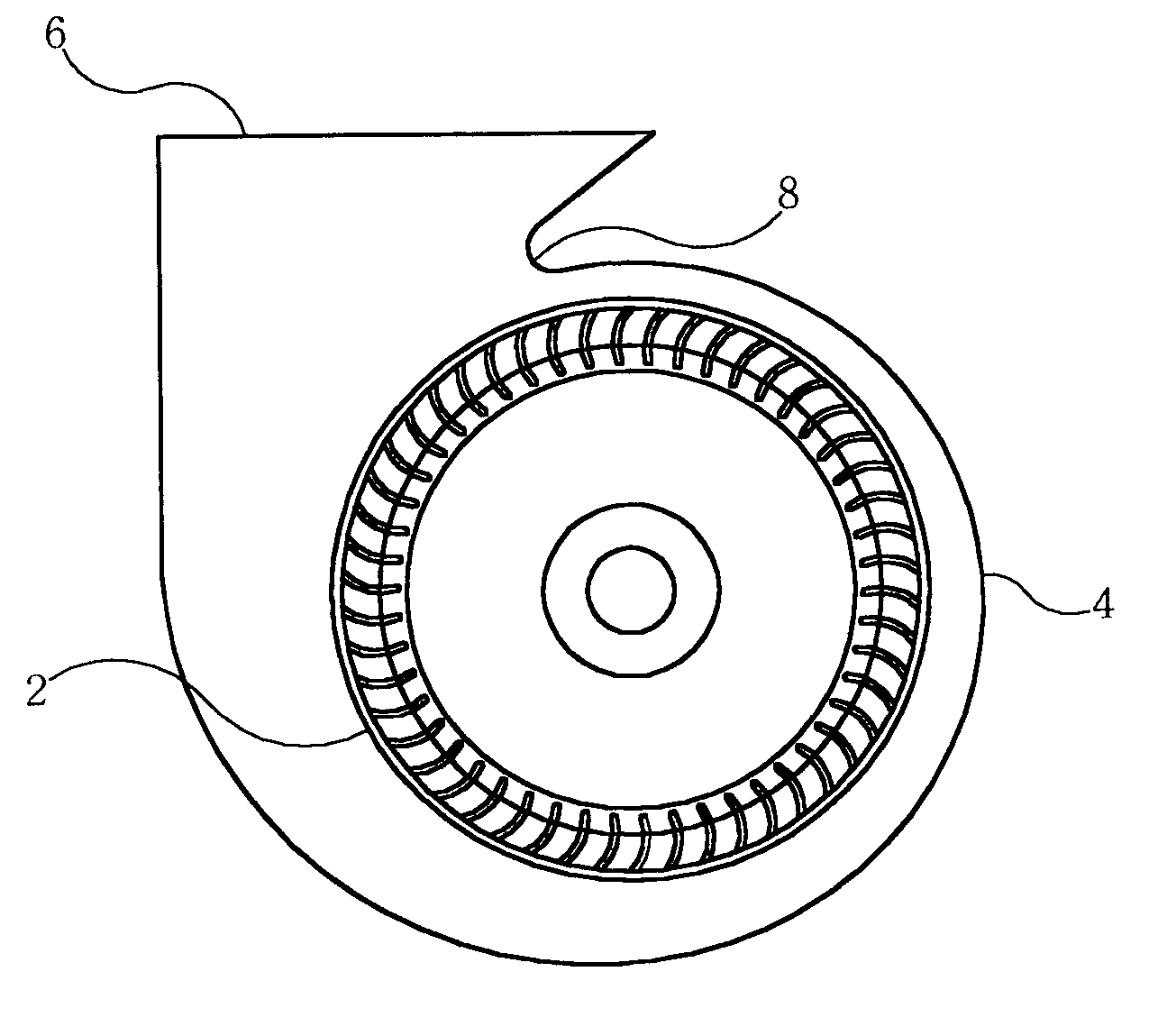
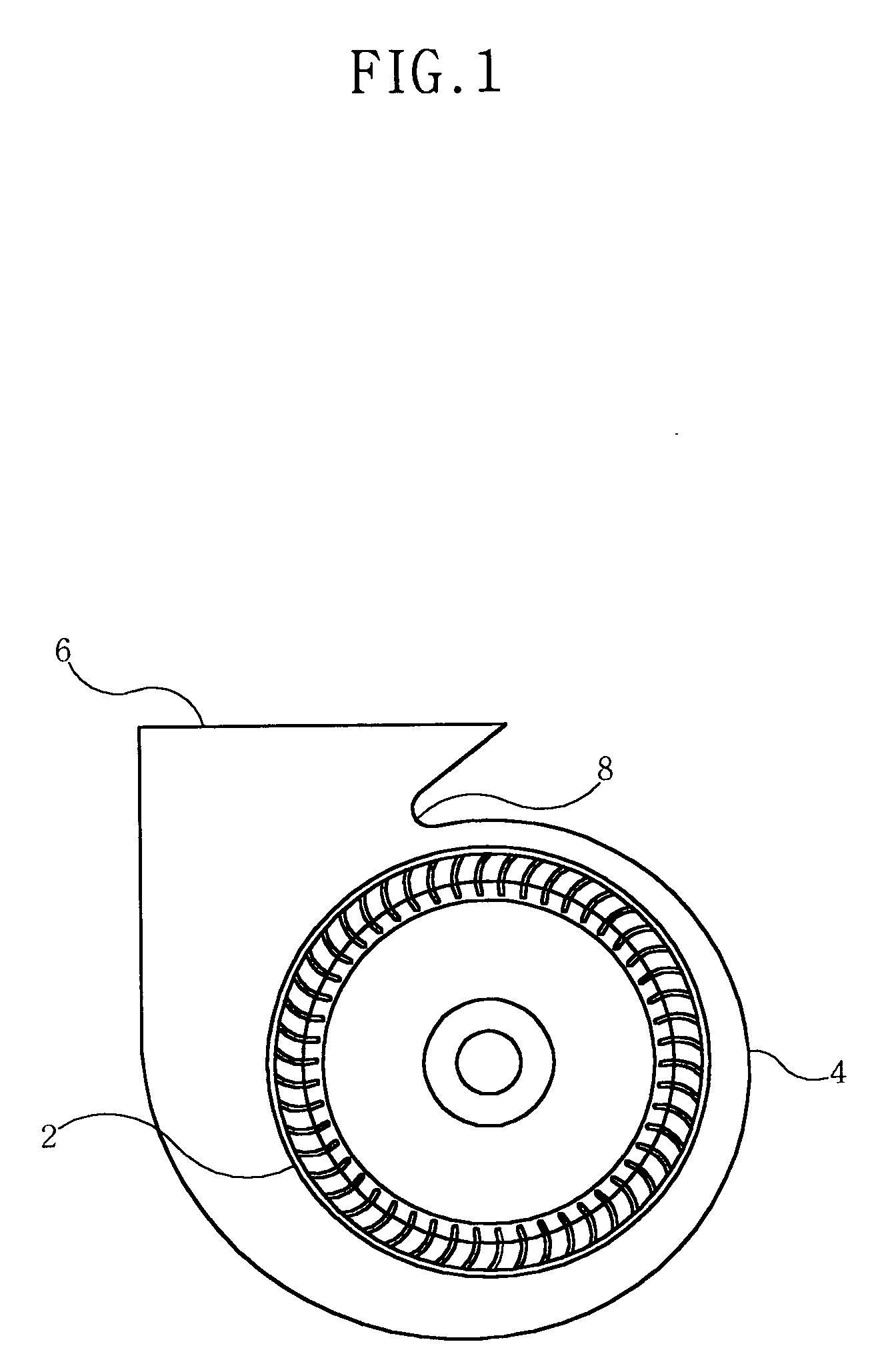
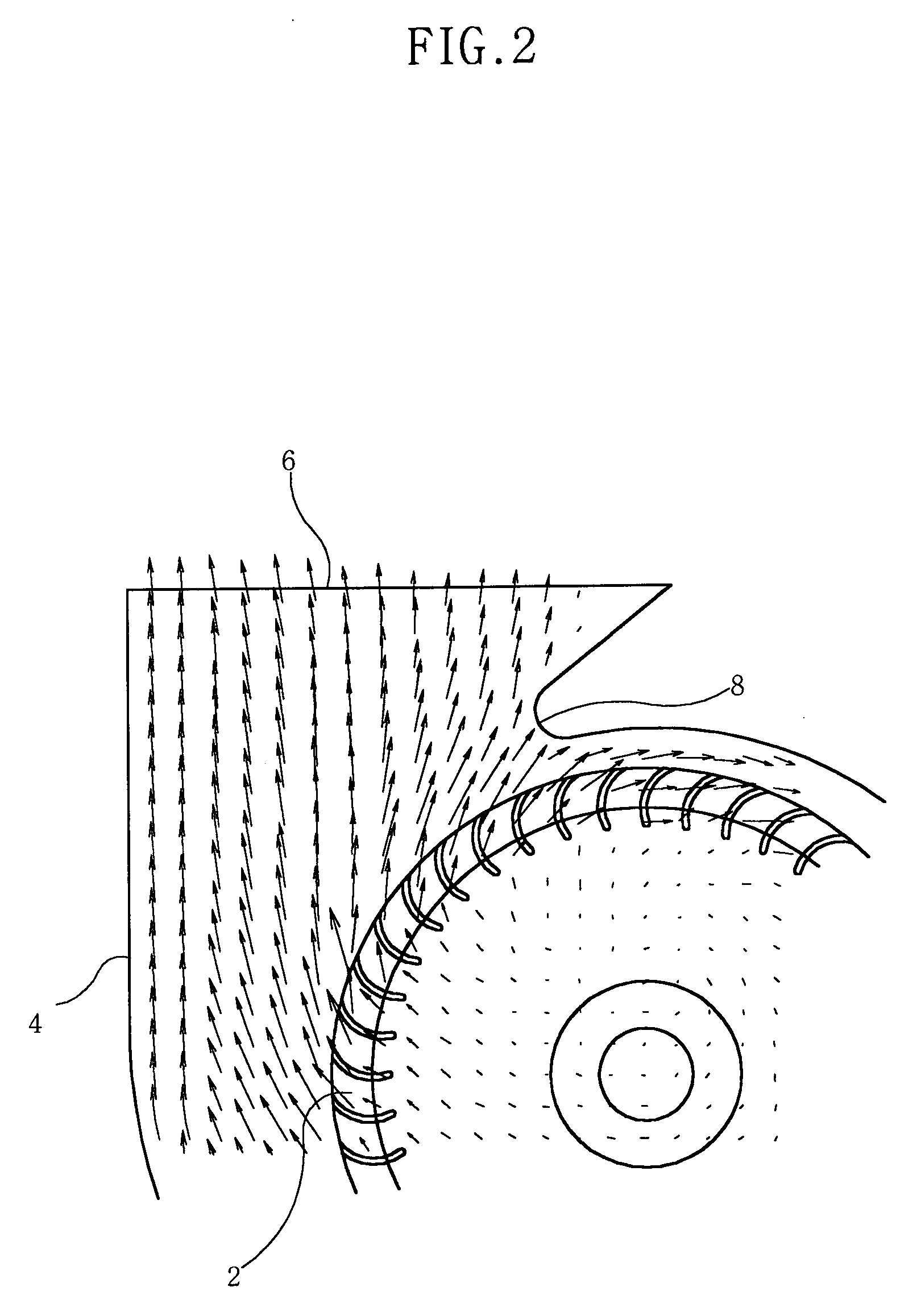
[0017] As shown in FIG. 4, a centrifugal blower, to which the present invention is applied, includes an impeller 12 which has a plurality of blades arranged in a circular shape, and a scroll casing 14 formed outside of the impeller 12 for forming a spiral flow path. The scroll casing 14 includes an inlet (not shown) which is formed at a predetermined position in the scroll casing 14 in the same direction as the axis of the impeller 12. Air is drawn into the scroll casing 14 through the inlet. The scroll casing 14 further includes an outlet 16 which is formed at a predetermined position in the scroll casing 14 in a direction perpendicular to the inlet, and a cut-off 18 for being provided between the impeller 12 and the outlet 16 for serving as a boundary between an outlet air flow field and an internal air flow field.

[0018] When the difference in pressure b...


PUM


Abstract

Disclosed herein is a scroll casing for centrifugal blowers provided outside of an impeller for forming a spiral air flow path, comprising: an outlet for discharging air; and a cut-off formed between the impeller and the outlet for serving as a boundary between an outlet air flow field and an internal air flow field wherein when a difference in pressure between an inlet and outlet of the centrifugal blower, indicated by a height of a water column, is designated by Δp (expressed in mm Aq), a water density is designated by ρ, a gravitational acceleration is designated by g, an outer diameter of the impeller is designated by D, and an angle of a circular arc defined from a position of the cut-off to a position where an expansion of the scroll casing ends is designated by θ (expressed in radians), an equation θ=(7π/4)−{(Δp)/(ρ g D)}×(π/180) is satisfied, thereby balancing the internal air flow and the outlet air flow even when a centrifugal blower is operated under high suction pressure condition, and thus, enhancing the performance of the centrifugal blower.

Description

BACKGROUND OF THE INVENTION [0001] 1. Field of the Invention [0002] The present invention relates generally to scroll casings for centrifugal blowers and, more particularly, to a scroll casing for centrifugal blowers which is used under a high suction pressure greater than atmospheric pressure. [0003] 2. Description of the Related Art [0004] Recently, according to industrial development, the public's interest in the environment has increased. As a result, new products, such as an air cleaner having an air blowing system, have been developed, and the application area of blowers has been expanded. Therefore, the development of a blower adapted for high suction pressure operation condition as well as atmospheric suction pressure operation condition (no load operation) is required. However, when the conventional centrifugal blowers is operated under high suction pressure condition, the efficiency thereof is reduced by 50% or more in comparison with when it is operated under atmospheric ...

Claims


Application Information

Patent Timeline
Patent Type & Authority Applications(United States)
IPC IPC(8): F03B3/16
CPCF01D9/026F04D29/422F05D2250/15B60N3/044B32B2307/21B32B2471/04B32B2307/202
Inventor KIM, JAE-WON
Owner IND UNIV COOP FOUND SUNMOON UNIV
Why Eureka
Try Eureka