Multifunctional dental mirror

Inactive Publication Date: 2006-07-27
TING SHAO CHIEH
View PDF10 Cites 30 Cited by
  • Summary
  • Abstract
  • Description
  • Claims
  • Application Information

AI Technical Summary

Benefits of technology

[0009] Yet another objective of the present invention is to provide the multifunctional dental mirror, wherein the stem of the intraoral viewing mirror is affixed to a ring, which enables rotating posit

Problems solved by technology

However, because of limitations imposed by size of the oral cavity after opening the mouth, and viewing-angle related problems, thus, the dentist is unable to directly see complete condition of the oral cavity of the patient.
However, because the light source is fixed at a certain position, if the size of the oral cavity of the patient is too small or the head of the patient is inclined to one side, then the light source is unable to project light onto the dental mirror, and thus there is no reflec

Method used


Image

  • Multifunctional dental mirror
  • Multifunctional dental mirror
  • Multifunctional dental mirror

Examples


Example

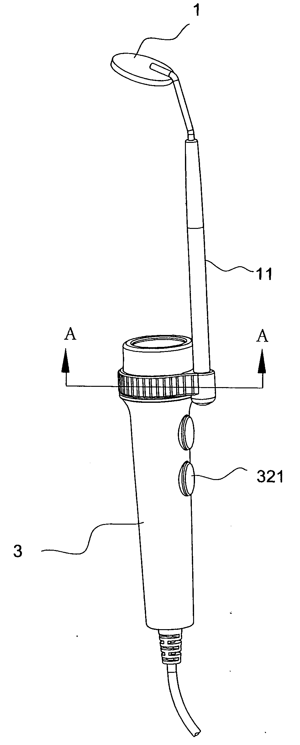
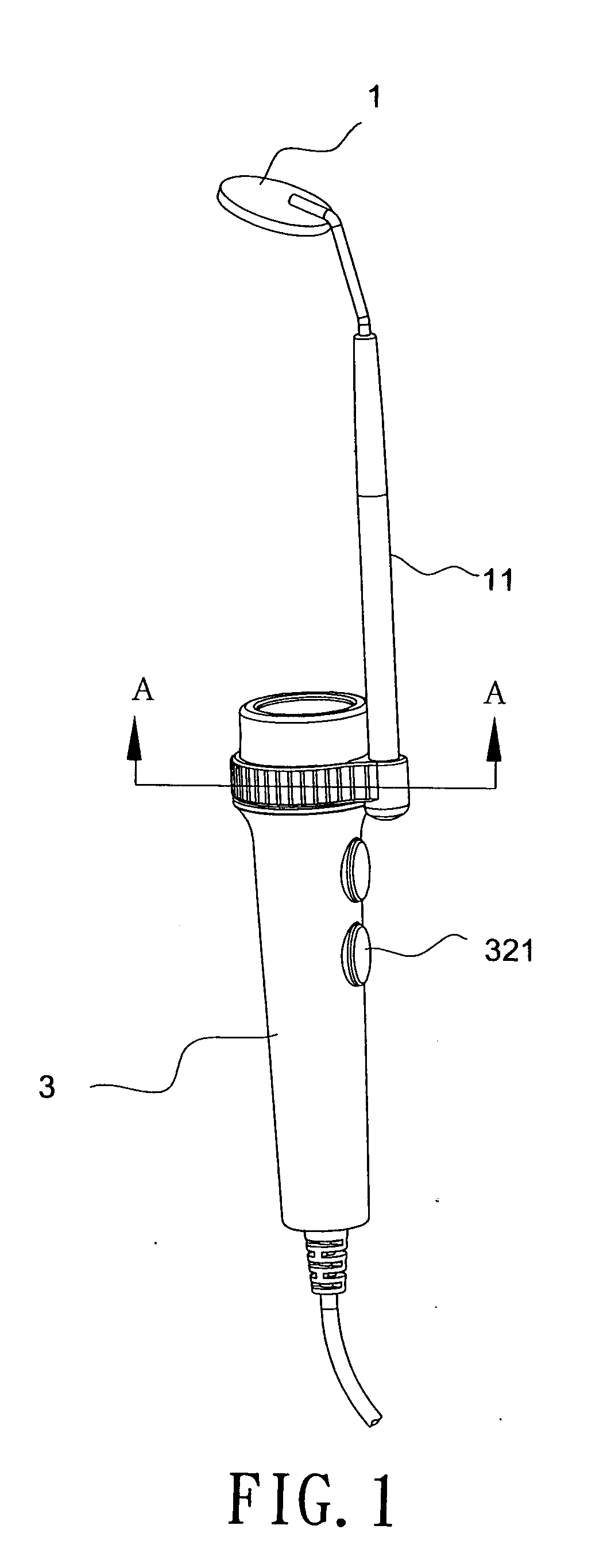
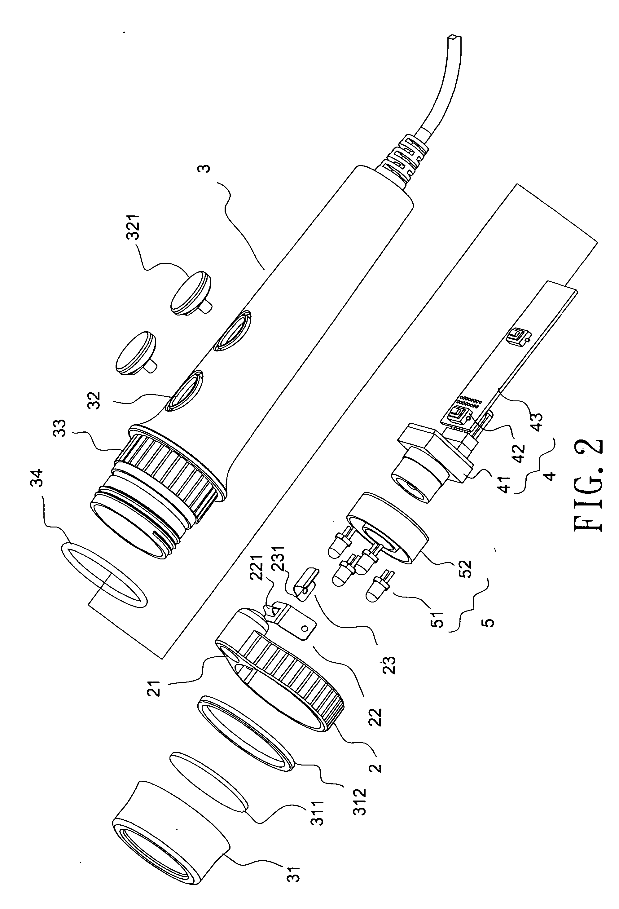
[0018]FIG. 1 shows an assembled elevational view of a preferred embodiment of the present invention, and in conjunction with the other FIGS., a multifunctional dental mirror of the present invention can be seen to comprise: an intraoral viewing mirror 1, a ring 2, a base 3, a camera device 4 and an LED (light-emitting diode) light-source device 5, wherein the intraoral viewing mirror 1 is connected to one end of a stem 11, and a groove 111 is defined in another end of the stem 11 (see FIG. 3). The ring 2 is disposed on the base 3, and a locating hole 21 is configured as an extension on a side of the ring 2, and provides for the intraoral viewing mirror 1 to be disposed and positionally fixed therein. A cover 31 is connected to the base 3, thereby forming a hollow containment cavity within the base 3, wherein electronic components are disposed. The cover 31 is an annular frame member, within which a transparent disk 311 is disposed. A water-repellent ring 34 and washer 312 are dispos...


PUM


Abstract

The present invention provides a multifunctional dental mirror, which is particularly applicable for use when examining or treating the oral cavity or teeth, and has a configuration encompassing a camera device and an LED light-source device. The light-source device projects light directly onto an intraoral viewing mirror, the light then undergoes reflection, thereby achieving effectiveness of illumination, and, in conjunction with circuitry connected to a computer or related display unit, real-time video image viewing or recording of video images from the intraoral viewing mirror is realized, which enables a user to know condition of the oral cavity or the teeth.

Description

BACKGROUND OF THE INVENTION [0001] (a) Field of the Invention [0002] The present invention relates to a multifunctional dental mirror, and more particularly to a dental mirror that enables a stomatologist or dentist to view deep into the oral cavity when examining a patient. [0003] (b) Description of the Prior Art [0004] Presently, the main objective of a dentist examining a patient is to examine outward appearance of the teeth and gums of the patient for abnormalities (such as: tartar, dental plaque, and so on), which is then used as a basis to make a diagnosis and determine whether or not to proceed with further medical treatment. However, because of limitations imposed by size of the oral cavity after opening the mouth, and viewing-angle related problems, thus, the dentist is unable to directly see complete condition of the oral cavity of the patient. Hence, the dentist must use a dental mirror in conjunction with a light source, which projects light into the oral cavity of the p...

Claims


Application Information

Patent Timeline
IPC IPC(8): A61C3/00
CPCA61B1/042A61B1/247A61C13/0004A61B1/0607A61B1/0669A61B1/0684
Inventor TING, SHAO-CHIEH
Owner TING SHAO CHIEH
Why Eureka
Try Eureka