Selective conductive interstitial thermal therapy device

a technology of conductive interstitial thermal therapy and conductive interstitial heat, which is applied in the field of body tissue treatment methods and devices, can solve the problems of inability to treat patients with such implants with rfa, inability to predict or easily control temperature, and interference with implants, so as to avoid life-threatening injuries, avoid interference, and easily control the maximum temperature

Inactive Publication Date: 2006-07-27
ARKANSAS CHILDRENS HOSPITAL RES INST
View PDF57 Cites 45 Cited by
  • Summary
  • Abstract
  • Description
  • Claims
  • Application Information

AI Technical Summary

Benefits of technology

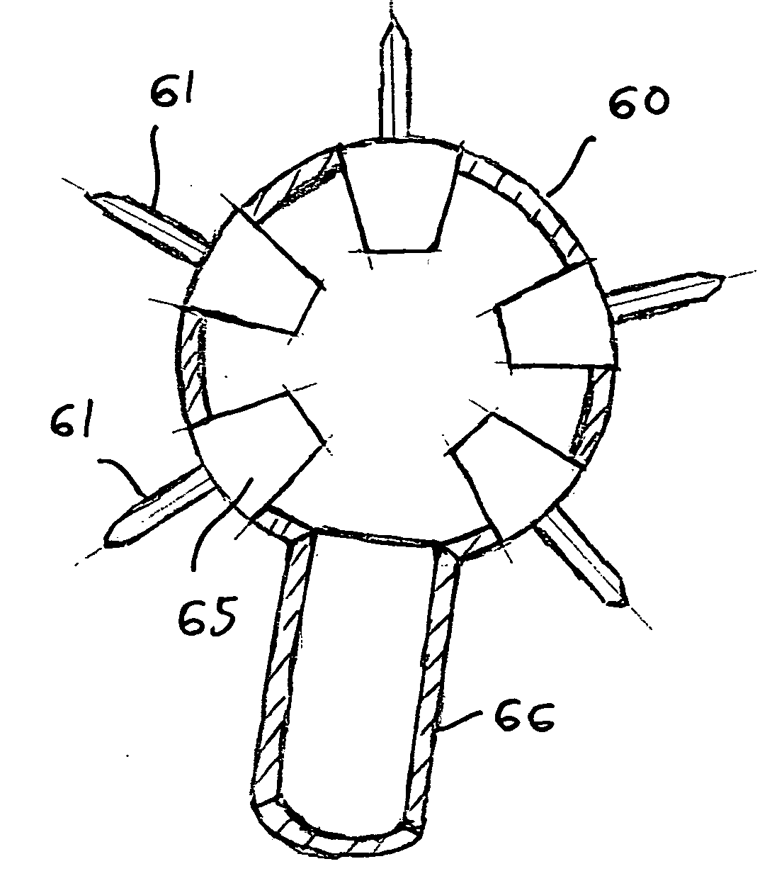
[0018] The present invention uses thermal conduction, as opposed to radiation absorption, to heat the tumor/lesion volume. Since the thermal properties of tissue are relatively homogenous, the results can be predicted. The shape of the probe tip in the form of the deployable thermal conductive elements may be altered during treatment. The combination of shape and activation temperature can be predetermined for any specific tumor/lesion geometry. This offers the following advantages: highly predictable temperature distribution; larger areas can be effectively treated, in a controlled manner, since the heat is dissipated primarily by conduction; localized carbonization will not result in tunneling and the process is safer than LLIT or RFA; the maximum temperature in the treatment zone will never exceed the temperature at the tip of the probe, and therefore, one can easily control the maximum temperature within the tumor/lesion and adjacent tissues; and temperature may be actively controlled via closed loop feedback system, where the maximum temperatures are measured during the process by placing miniature thermocouples at the end of the thermal probe.
[0019] In an alternative embod

Problems solved by technology

However, as discussed above, in the LLIT and RFA processes, the temperature cannot be predicted or easily controlled due to the varying light and RF energy absorption p

Method used


Image

  • Selective conductive interstitial thermal therapy device
  • Selective conductive interstitial thermal therapy device
  • Selective conductive interstitial thermal therapy device

Examples


Embodiment Construction

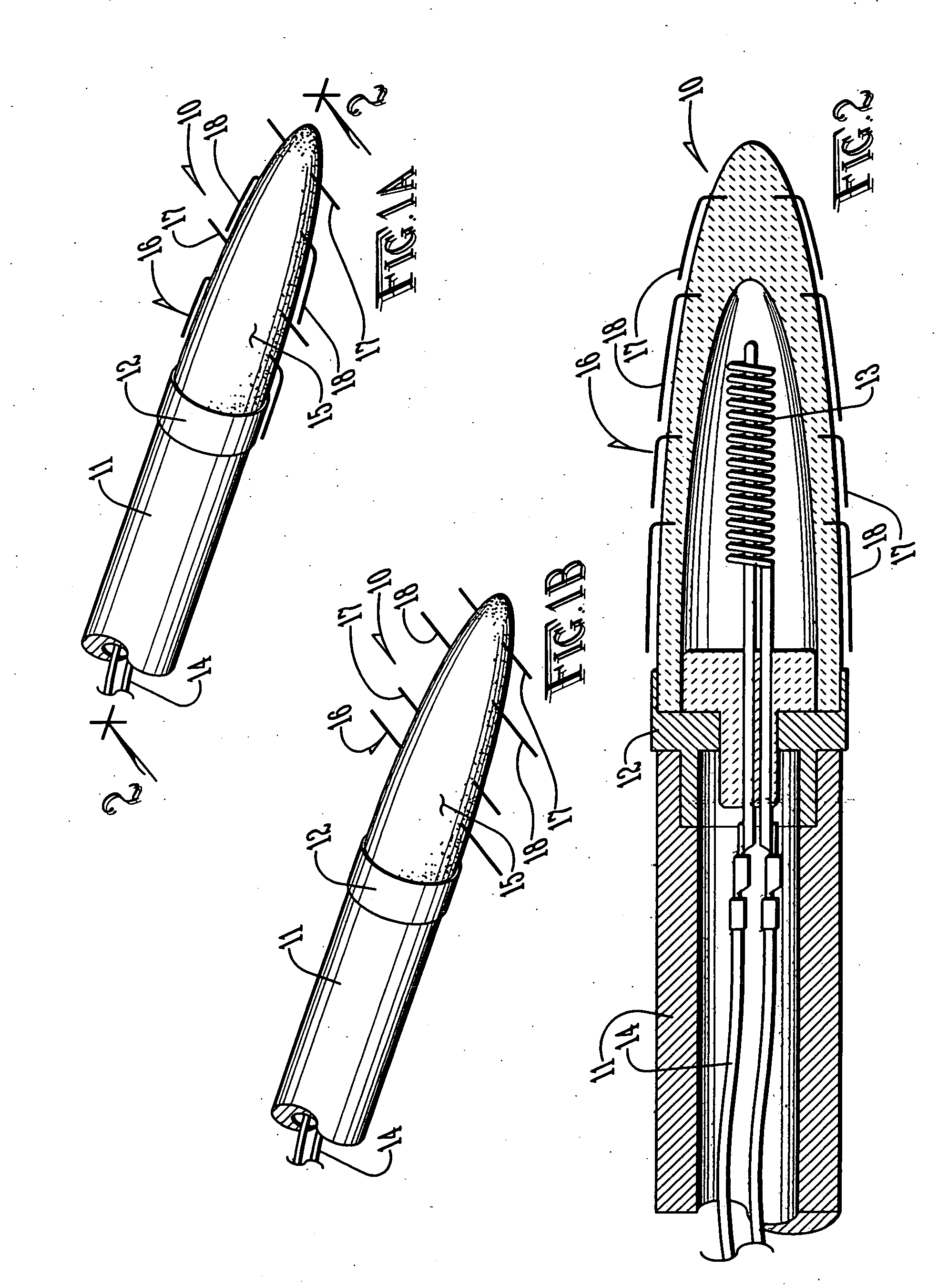
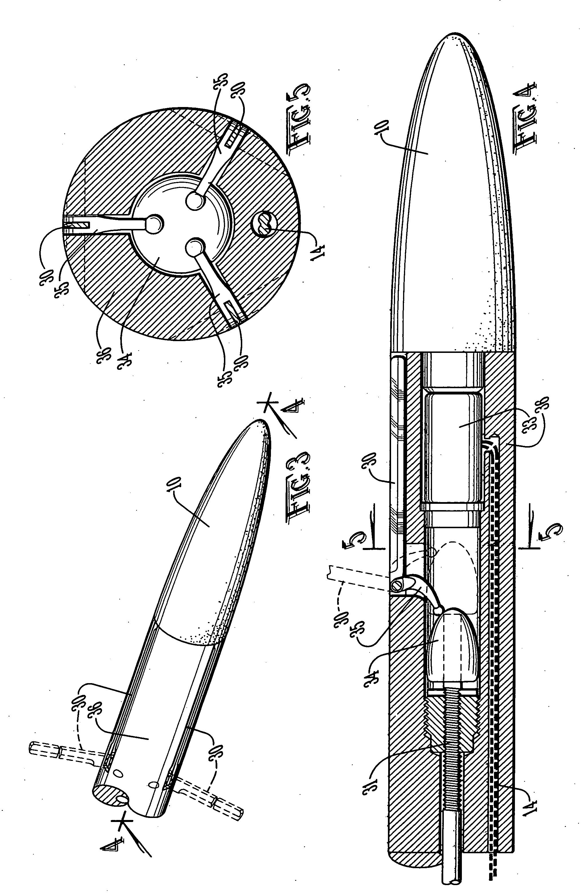
[0040] With reference to FIGS. 1A-12, the preferred embodiments of the present invention may be described as follows.

[0041] The present invention is a miniature thermal apparatus for the controlled destruction of malignant and benign tumors / lesions and abnormal or excess tissue. As used herein, the terms tumors and lesions may be used interchangeably to indicate tissue to be thermally treated by the device and method of the present invention. The present invention comprises a tip 10 mounted onto a fiber 11 that can be inserted through a catheter that has been accurately placed within the tumor / lesion. The tumor / lesion is destroyed via heat generation originating from the specifically designed tip 10 that matches the tumor / lesion geometry. The tip 10 comprises a plurality of deployable thermal conductive elements that may be customized by the number, size and arrangement to be deployable into a geometry that matches the geometry of the tumor / lesion to be thermally treated. The tempe...


PUM


Abstract

An apparatus and method for thermally destroying tumors. A tip has a plurality of deployable thermal conductive elements whose temperatures are individually controllable. This allows the shape of the thermal field to be controlled and for specific areas to be protected from excessive heat by cooling those specific areas while ablating other areas. In another embodiment, the deployable thermal conductive elements are individually deployable to various lengths to further aid in shaping the thermal field. The temperatures and the shape of the thermal field may be monitored and controlled by a data processing device, such as a microprocessor. Further selectivity in defining the area of tissue to be treated may be achieved by introducing into the tissue thermal additives that alter the thermal properties of the tissue.

Description

CROSS-REFERENCE TO RELATED APPLICATIONS [0001] This application is a continuation-in-part of pending U.S. patent application Ser. No. 11 / 028,157, filed Jan. 3, 2005, which is a continuation of U.S. patent application Ser. No. 10 / 336,973 filed Jan. 6, 2003, now U.S. Pat. No. 6,872,203, which is a continuation-in-part of U.S. patent application Ser. No. 10 / 228,482 filed Aug. 27, 2002, now U.S. Pat. No. 6,780,177, all of which are incorporated herein by reference.STATEMENT REGARDING FEDERALLY SPONSORED RESEARCH OR DEVELOPMENT [0002] Not applicable. BACKGROUND OF THE INVENTION [0003] 1. Field of the Invention [0004] The present invention relates to methods and devices for treating body tissues such as tumors or lesions with thermal energy, and in particular, to such methods and devices that deploy thermally conductive elements to treat a predetermined shape of tissue. [0005] 2. Brief Description of the Related Art [0006] Within the last ten years, interstitial thermal therapy of tumors ...

Claims


Application Information

Patent Timeline
IPC IPC(8): A61B18/04
CPCA61B2017/00867A61B18/082A61B18/24A61B18/20A61B2018/00011A61B2018/00791A61B2018/2005A61B2018/00577A61B2017/00101A61B2017/00084A61B2018/00714
Inventor SHAFIRSTEIN, GAL
Owner ARKANSAS CHILDRENS HOSPITAL RES INST
Why Eureka
Try Eureka