Apparatus and method for encoding an audio signal and apparatus and method for decoding an encoded audio signal

a technology of encoder and audio signal, applied in the field of encoder methods, can solve the problems of only being considered stationary for very short time periods, affecting the frequency solution, etc., and achieve the effects of improving the quality of the first encoder method, good time resolution, and well and efficiently captured

Active Publication Date: 2006-07-27
DOLBY INT AB
View PDF15 Cites 15 Cited by
  • Summary
  • Abstract
  • Description
  • Claims
  • Application Information

AI Technical Summary

Benefits of technology

[0024] According to the invention, the quality of the first encoder method is improved by the second encoder, by performing a difference formation between the output signal of the first encoder / decoder path and the original audio signal, and that then the resulting residual signal is encoded with the second encoder, which has a good time resolution. This encoding is particularly favorable for the residual signal, since it already comprises few tonal elements, since they have already been very well and efficiently captured by the first encoding method.
[0025] The significant deficiency of this residual signal, however, is the bad time resolution, which shows in the generation of noise prior or after a transient, i.e. a pre-echo or post-echo. Pre-echos are more disturbing than post-echos, since they are easily detectable for a subjective. So to speak, this noise is the quantizing noise of the transient and corresponds in its spectral content mainly to the one of the transient and is thus not tonal. Thus, by using the transform encoding method with shorter blocks, i.e. with a high time resolution, the time resolution is considerably improved in an efficient way.
[0026] Thus, according to the invention, an audio encoding method with high and highest quality is obtained, by detecting the portions of the audio signal, which are tonal or rather tonal, with a frequency-selective transform encoding method with long transform lengths, while a downstream encoding method with short transform length enables a high time resolution for the residual signal.

Problems solved by technology

If the shorter portions of the audio signal were converted into the spectral range for increasing the time resolution, this would lead to the fact that the frequency solution suffers correspondingly.
Therefore, it is a problem that audio signals can only be considered stationary for very short time periods.

Method used


Image

  • Apparatus and method for encoding an audio signal and apparatus and method for decoding an encoded audio signal
  • Apparatus and method for encoding an audio signal and apparatus and method for decoding an encoded audio signal
  • Apparatus and method for encoding an audio signal and apparatus and method for decoding an encoded audio signal

Examples


Embodiment Construction

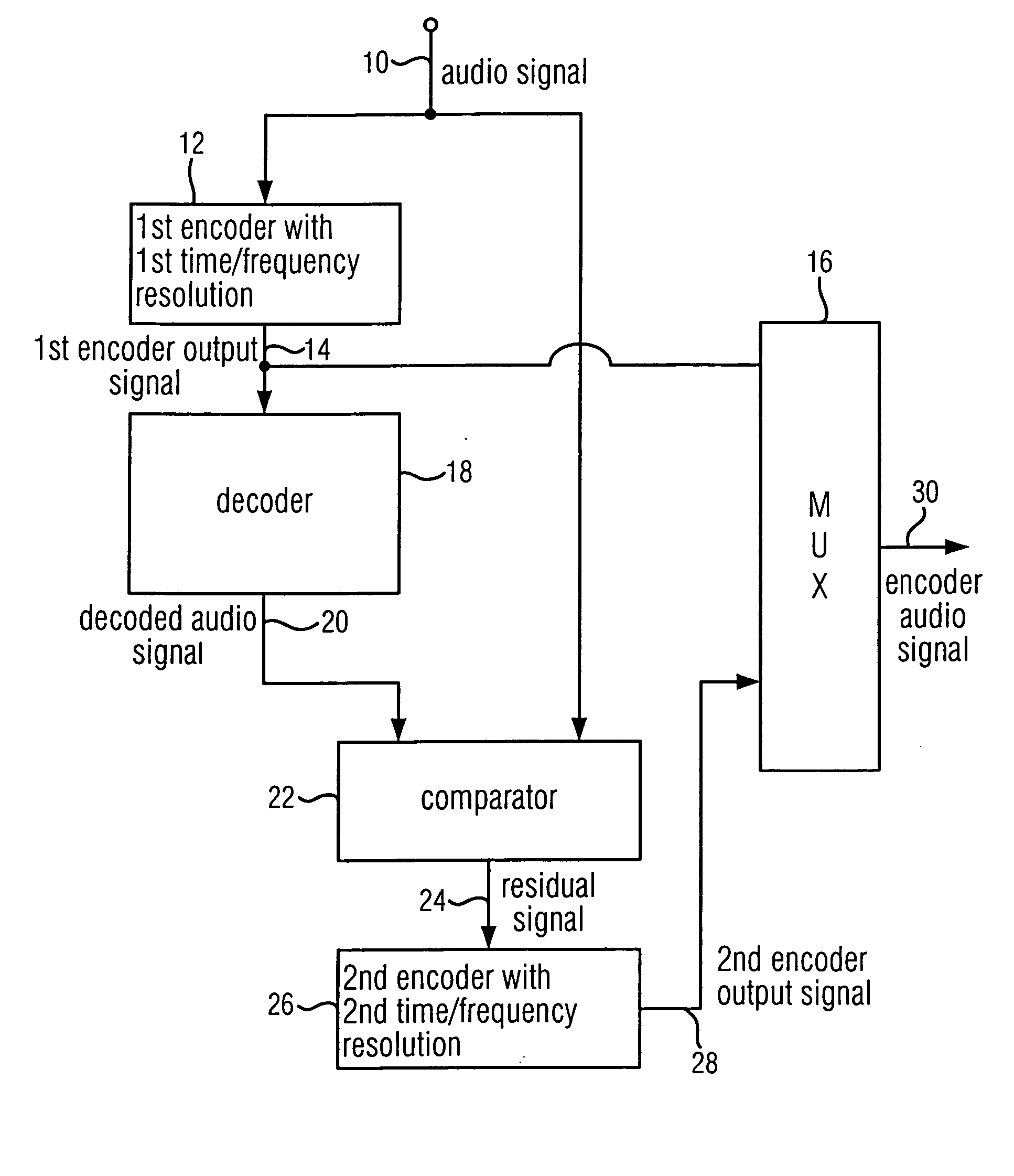
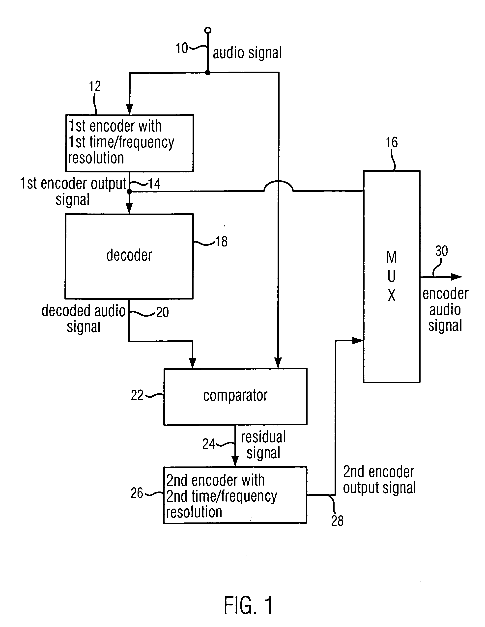
[0033]FIG. 1 shows an apparatus for encoding an audio signal, which is provided via input 10. First, the audio signal is fed into a first encoder 12 with a first time / frequency resolution. The first encoder 12 is formed to generate a first encoder output signal at an output 14. The first encoder output signal at output 14 of the first encoder 12 will be supplied, on the one hand, to a multiplexer 16, and, on the other hand, to a decoder 18, which is adapted to the first encoder and decodes the first encoder output signal to provide a decoded audio signal at an output 20 of the decoder 18. The decoded output signal 20 as well as the original audio signal 10 is supplied to a comparator 22. The comparator 22 is formed to compare the audio signal at the input 10 to the decoded audio signal at the output 20, which means after the path from the first encoder 12 and decoder 18. The comparator 22 is particularly formed to provide a residual signal at one of its outputs 24, wherein the resid...


PUM


Abstract

When encoding an audio signal, the audio signal is first encoded with the first encoder to obtain a first encoder output signal. This first encoder output signal is written into a bit stream. It is further decoded by a decoder to provide a decoded audio signal. The decoded audio signal is compared with the original audio signal to obtain a residual signal. The residual signal is then encoded via a second encoder to provide a second encoder output signal which is also written into a bit stream. The first encoder has a first time or frequency resolution. The second encoder has a second time or frequency resolution. The first resolution differs from the second resolution, so that in a respective decoder, an audio signal with both a high time resolution as well as a high frequency resolution can be retrieved.

Description

CROSS-REFERENCE TO RELATED APPLICATION [0001] This application is a continuation of copending International Application No. PCT / EP04 / 006850, filed Jun. 24, 2004.BACKGROUND OF THE INVENTION [0002] 1. Field of the Invention [0003] The present invention relates to encoding techniques and particularly to audio encoding techniques. [0004] 2. Description of the Related Art [0005] Audio encoders, and particularly such encoders known under the keyword “mp3”, “AAC” or “mp3PRO” have recently gained wide acceptance. They allow the compression of audio signals, which require a significant amount of data, when they are present, for example, in PCM format on an audio CD, to “tolerable” data rates, which are suitable for the transmission of the audio signals across channels with limited bandwidth. Thus, for transmitting data in the PCM format, data rates of up to 1.4 Mbit / s are required. “mp3”-encoded audio data achieve already a stereo sound with high quality at data rates of 128 kbit / s. [0006] F...

Claims


Application Information

Patent Timeline
Patent Type & Authority Applications(United States)
IPC IPC(8): G10L19/00G10L19/02G10L19/022G10L19/24
CPCG10L19/0212G10L19/022G10L19/24
Inventor HOERICH, HOLGERSCHUG, MICHAELNEUSINGER, MATTHIAS
Owner DOLBY INT AB
Why Eureka
Try Eureka