Apparatus and methods for repairing compressor airfoils in situ

a compressor and in situ technology, applied in the direction of machines/engines, manufacturing tools, liquid fuel engines, etc., can solve the problems of reducing the service life of the compressor, so as to maximize the impact of the steel shot and strengthen the surface

Inactive Publication Date: 2006-08-03
GENERAL ELECTRIC CO
View PDF18 Cites 14 Cited by
  • Summary
  • Abstract
  • Description
  • Claims
  • Application Information

AI Technical Summary

Benefits of technology

[0004] More particularly, first, second and third modules, which are driven in the coordinate directions X, Y and Z by lead screws, are mounted to the manipulator. The lead screws are under servo-motor control so that the position of the work head is known at all times. The manipulator and the various modules are driven remotely from a control station through a controller, for example, using a joystick for manual operation or using motion control software enabling the work head to be moved in a specified repeatable manner with automated patterns. The motion control system provides continuous feedback of work head position. Stabilizing rams may be interconnected between the manipulator and the outer casing of the compressor inlet to lock the manipulator in a desired location to provide a stable platform for repairing selected airfoils.
[0006] The repaired surface is then inspected, for example, by mounting a camera on the third module carried by the manipulator, or using a hand-held camera and inserting the camera into the first stage of the compressor to view the repaired surface. If the surface is properly repaired, it is then strengthened by shot peening. To accomplish this, the abrasion tool or fillet area tool is removed from the third module and replaced with a tool which is provided with a flapper for captive shot peening. Alternatively, the fillet area tool may be configured such that the cylindrical abrasive work head may be removed and replaced with a flapper peening work head. The flapper per se is commercially available and comprises a plurality of steel shot embedded or secured in a rectangular piece of flexible material such as a woven cloth-type material. The flapper work head is mounted in the flapper peening tool for rotation about a central axis whereby the steel shot carried by the flapper periodically impacts the airfoil surface as the flapper is rotated. The impact of the steel shot against the airfoil surface provides residual compressive stresses in the surface and strengthens the surface. With the known measurements of the airfoil section previously recorded, the shot peening flapper may be positioned to maximize the impact of the steel shot against the surface and to follow the repaired surface such that selected areas of the surface are strengthened.

Problems solved by technology

Machine components such as gas turbine airfoils can experience damage in use or during installation.
For example, one type of damage, blade erosion, particularly occurs about the leading edge portions of the rotating blades.
Manual repair methods that require the removal of compressor casings and enclosures are costly and time-consuming processes.
Process consistency is not assured in those repairs.
In addition, substantial time and costs are necessary to disassemble and reassemble the turbine components.

Method used


Image

  • Apparatus and methods for repairing compressor airfoils in situ
  • Apparatus and methods for repairing compressor airfoils in situ
  • Apparatus and methods for repairing compressor airfoils in situ

Examples


Embodiment Construction

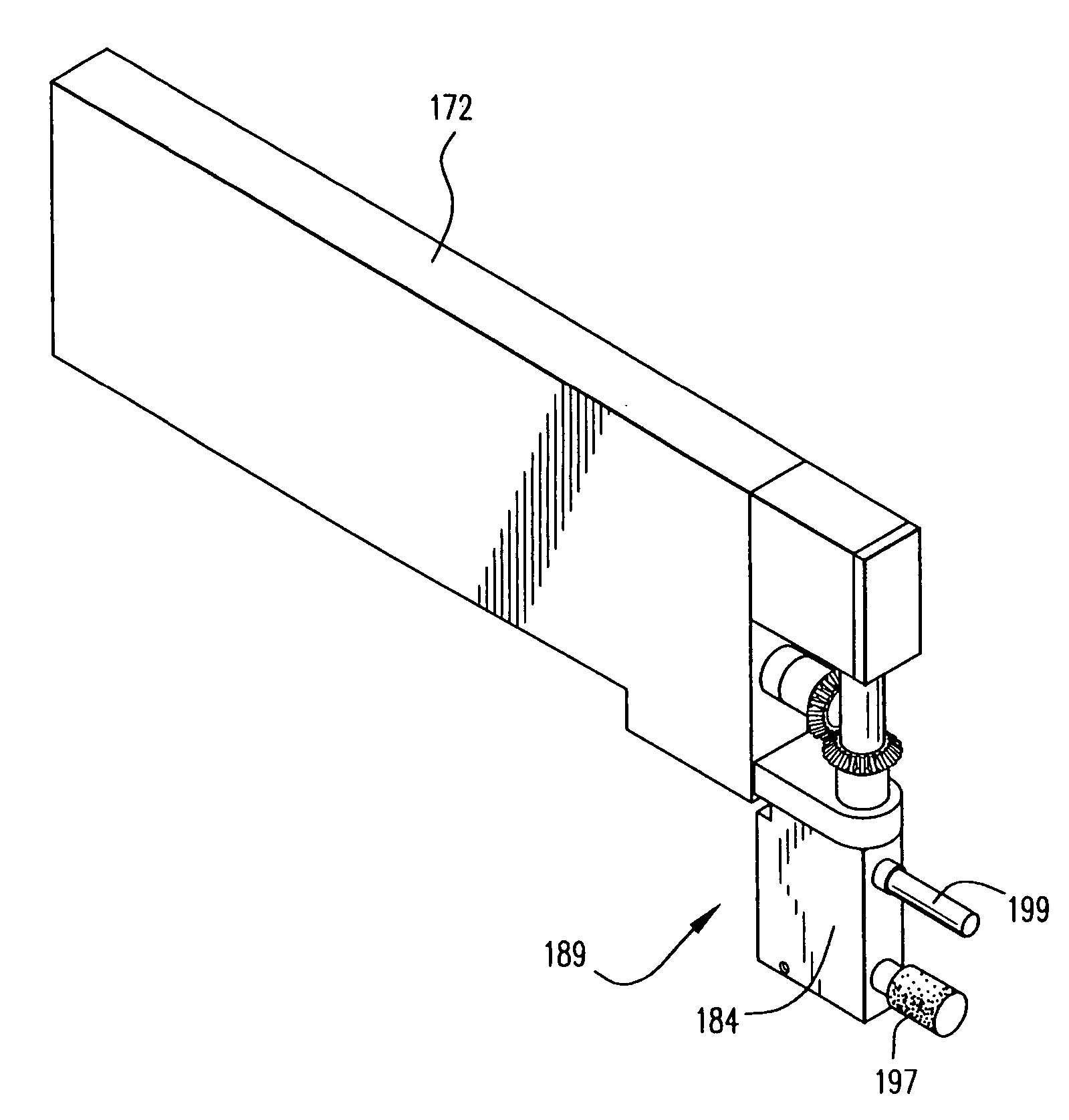
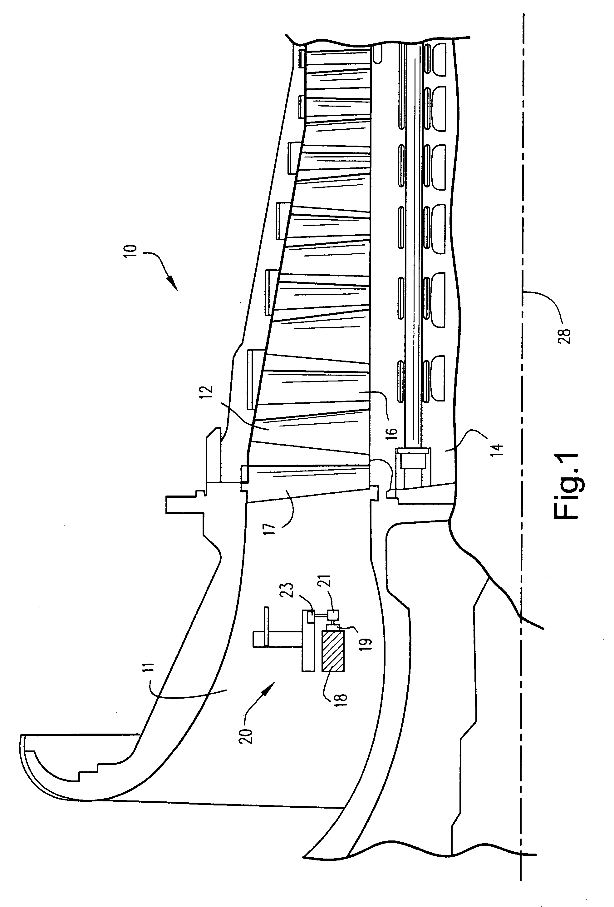
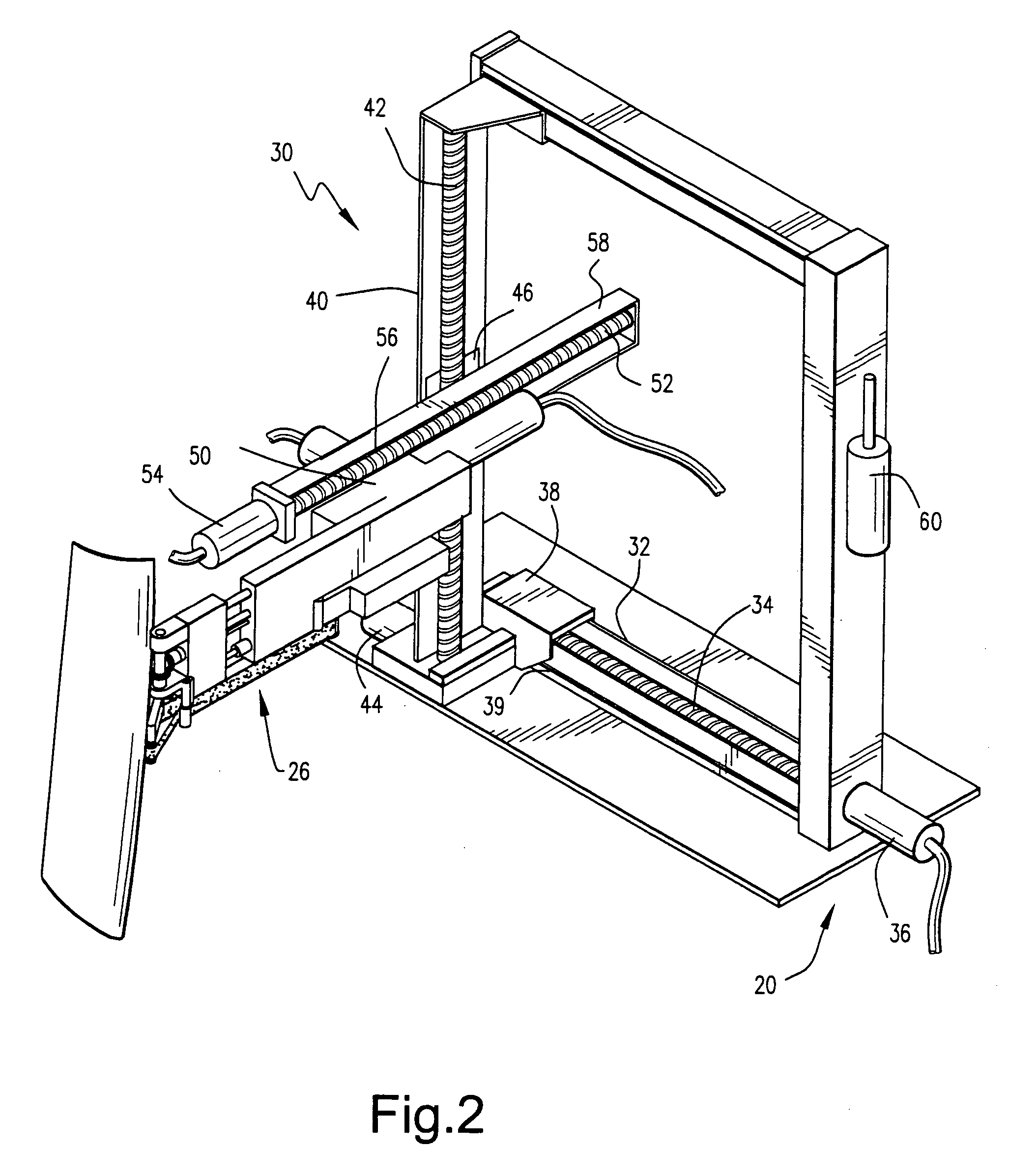
[0030] Referring now to the drawings, particularly to FIG. 1, there is illustrated in a fragmentary cross-sectional view a compressor, generally designated 10, including an inlet portion 11. Compressor airfoils 12 are mounted on a rotor 14 with intervening stator vanes 16, the rotor being rotatable about axis 28. As illustrated, an annular track 18 is mounted in the inlet portion 11 of the compressor 10, e.g., clamped to the inlet cone or inner diameter, just upstream of the stationary inlet vanes 17. A manipulator, generally indicated 20, is mounted on the track for movement circumferentially about the track. The track 18 has gear teeth 19 for engaging corresponding gear teeth 21 driven by a servo-motor 23 carried by the manipulator 20. Thus, by driving the gear 21 on the manipulator 20, the manipulator 20 may be driven to any rotational position about the inlet of the compressor and the track. By employing a servo-motor under computer control, the circumferential position of the m...


PUM

PropertyMeasurementUnit
timeaaaaaaaaaa
diameteraaaaaaaaaa
distanceaaaaaaaaaa

Abstract

The apparatus includes a track mounted in the inlet of a compressor. A manipulator is mounted for movement about the track and carries three modules, the last of which mounts a tool head for movement in a Cartesian coordinate system and about the track. A measuring head measures the location of the airfoil surface. An abrading tool mounted on the third module removes surface material from the airfoil. Subsequently, a shot-peening device, either a flapper with embedded shot or free shot is impacted against the abraded surface to strengthen the surface. Final inspection is performed by a light and camera head mounted on the third module.

Description

BACKGROUND OF THE INVENTION [0001] The present invention relates to automated repair of damaged airfoils on turbines and particularly relates to a computer-controlled mechanical manipulator for measuring, inspecting and repairing airfoil blades in situ. [0002] Machine components such as gas turbine airfoils can experience damage in use or during installation. For example, one type of damage, blade erosion, particularly occurs about the leading edge portions of the rotating blades. Manual repair methods that require the removal of compressor casings and enclosures are costly and time-consuming processes. While processes using hand-held tools, such as grinding and sanding tools, have been developed and utilized for the purpose of repairing airfoils, the quality of the manual repairs depends on the skill and attention of the craftsman performing the work. Process consistency is not assured in those repairs. In addition, substantial time and costs are necessary to disassemble and reasse...

Claims


Application Information

Patent Timeline
Patent Type & Authority Applications(United States)
IPC IPC(8): B23P6/00B21D39/02B24C1/04B24B19/14B24B21/16B24B21/18B24B39/02F01D5/00F04D29/64
CPCB23P6/002B24B19/14B24B21/16B24B39/026F01D5/005Y10T29/49238Y10T29/49336Y10T29/53039Y10T29/49318Y10T29/49748Y10T29/4511Y10T29/53061Y10T29/47B24C1/10B24C5/02B23P6/00
Inventor MCCARVILL, JOHNLAWSON, RONALD H. JR.ROZIER, ELENABOUSQUET, MICHAELHATLEY, RICHARD M.HATLEY, KENNETH J.
Owner GENERAL ELECTRIC CO
Why Eureka
Try Eureka