Eureka AIR delivers breakthrough ideas for toughest innovation challenges, trusted by R&D personnel around the world.

Engine intake manifold and airflow control valve assembly

Inactive Publication Date: 2006-08-03
MANN HUMMEL GMBH
View PDF2 Cites 2 Cited by
  • Summary
  • Abstract
  • Description
  • Claims
  • Application Information

AI Technical Summary

Benefits of technology

[0008] In accordance with one aspect of the invention, an engine intake manifold includes a casing having a plurality of air intake passages, and a plurality of valve plates, wherein each valve plate is disposed in one of the air intake passages to control airflow through the air intake passage. The valve plates are connected to a common valve shaft for rotation between an open position and a closed position. The engine intake manifold may further include an actuator that is mounted to the casing via a snap connection and is rotationally connected to the valve shaft to allow the actuator to rotate the valve shaft. The snap connection has several advantages. For example, it eliminates the need for screws and makes it easier to assemble the intake manifold, resulting in cost reduction and increased efficiency.
[0010] In another preferred embodiment, the indentation is a circular groove and the protrusion is a circular protrusion, and the circular groove and the circular protrusion are configured so that, when they are engaged, they secure the casing sleeve inside the actuator sleeve to form a snap connection. Preferably, the circular protrusion and circular groove are sufficiently flexible so that the circular protrusion can be easily snapped into the circular groove. To that end, the actuator sleeve may include one or more axial grooves to increase the flexibility of the circular protrusion or the circular groove on the actuator sleeve's inner surface.
[0014] The snap connection may include a cavity and a member that can extend into the cavity. The cavity can be disposed at either a valve shaft end or the actuator, and the member can be disposed at the other of the valve shaft end and actuator. One of the cavity and member may include an indentation, and the other of the cavity and member may include a protrusion. When the member extends into the cavity, the protrusion can engage the indentation to secure the member inside the cavity and to rotationally connect the member and cavity to each other so that the actuator can rotate the valve shaft.
[0015] In a preferred embodiment of the invention, the member is an cylindrical end of the valve shaft, and the cavity is the hollow interior of a sleeve belonging to the actuator, wherein the cylindrical end of the valve shaft is extendable into the sleeve in the axial direction. Furthermore, the indentation of the preferred embodiment may be a circular groove, and the protrusion may be a circular protrusion. The circular protrusion and the circular groove preferably are sufficiently flexible so that the circular protrusion can be snapped into the circular groove. To increase the flexibility of the circular protrusion or the circular groove, the sleeve may include at least one axial groove intersecting the circular protrusion or the circular groove on the sleeve's inner surface. Similarly, the cylindrical end of the valve shaft can be made hollow and can also include at least one axial groove intersecting the circular protrusion or the circular groove.

Problems solved by technology

Therefore, the air passages of the intake manifold are often configured to achieve a balanced engine performance over the entire range of engine operation, but less than optimum engine performance at each engine operating condition.

Method used


Image

  • Engine intake manifold and airflow control valve assembly
  • Engine intake manifold and airflow control valve assembly
  • Engine intake manifold and airflow control valve assembly

Examples


Embodiment Construction

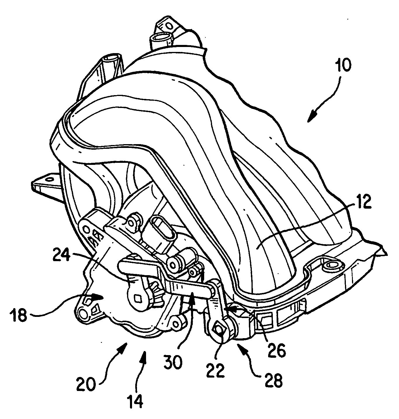
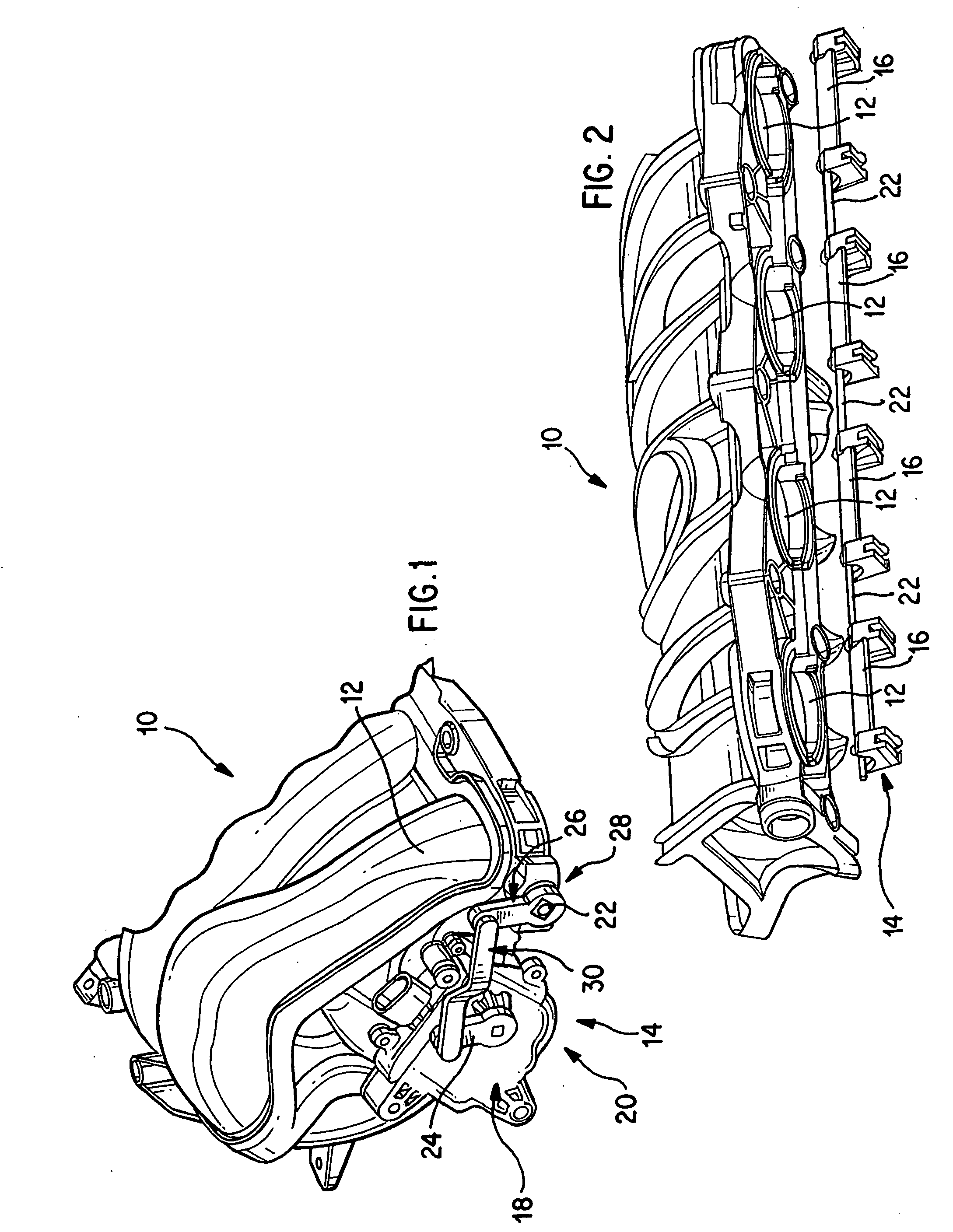
[0023]FIGS. 1 and 2 illustrate a preferred engine intake manifold 10 of the present invention. The engine intake manifold 10 includes a plurality of air intake passages 12 and an airflow control valve assembly 14 that is used to control the airflows through the air intake passages 12. In FIG. 2, the airflow control valve assembly 14 is shown separate from a section of the intake manifold which is designed to receive the airflow control valve assembly14. As shown in FIG. 2, the airflow control valve assembly 14 has a plurality of valve plates 16, and each valve plate 16 is disposed in an air intake passage 12 to control the airflow through the air intake passage 12. The airflow control valve assembly 14 also includes a valve shaft 22 connected to the valve plates 16 to rotate the valve plates 16 between an open position and a closed position.

[0024] Further, as shown in FIG. 1, the airflow control valve assembly 14 also includes an actuator 18 and a four-bar linkage 20 that is used t...


PUM


Abstract

An engine intake manifold includes a casing having a plurality of air intake passages, and a plurality of valve plates, wherein each valve plate is disposed in one of the air intake passages to control airflow through the air intake passage. The valve plates are connected to a common valve shaft for rotation between an open position and a closed position. The engine intake manifold may further include an actuator that is mounted to the casing or to the valve shaft via a snap connection, and is rotationally connected to the valve shaft to allow the actuator to rotate the valve shaft.

Description

[0001] This application claims the benefit of U.S. Provisional Patent Application No. 60 / 642,668, filed Jan. 11, 2005, the entire disclosure of which is incorporated herein by reference.FIELD OF THE INVENTION [0002] The present invention relates to an intake manifold for an internal combustion engine and to an airflow control valve assembly for an engine intake manifold. BACKGROUND OF THE INVENTION [0003] The operation of a typical engine intake system is well known. In a typical internal combustion engine, air enters the engine's intake manifold through a throttle body. The throttle body generally has one throttle valve that regulates the amount of air entering the intake manifold. Once the air is inside the intake manifold, it flows through the intake manifold's air passages into the combustion chambers of the engine.. In the intake manifold, the air mixes with fuel, and the air / fuel mixture is introduced into the combustion chambers of the engine for combustion. [0004] How well t...

Claims


Application Information

Patent Timeline
IPC IPC(8): F02D9/10F02M35/10
CPCF02B31/085F02D9/1065F02M35/10144F02M35/10255F02M35/10354Y02T10/146Y02T10/12
Inventor VICHINSKY, KEVIN
Owner MANN HUMMEL GMBH
Why Eureka
Eureka Blog
Learn More