
Drive device of display panel

Inactive Publication Date: 2006-08-03
ZIPPY TECH
View PDF8 Cites 2 Cited by
  • Summary
  • Abstract
  • Description
  • Claims
  • Application Information

AI Technical Summary

Benefits of technology

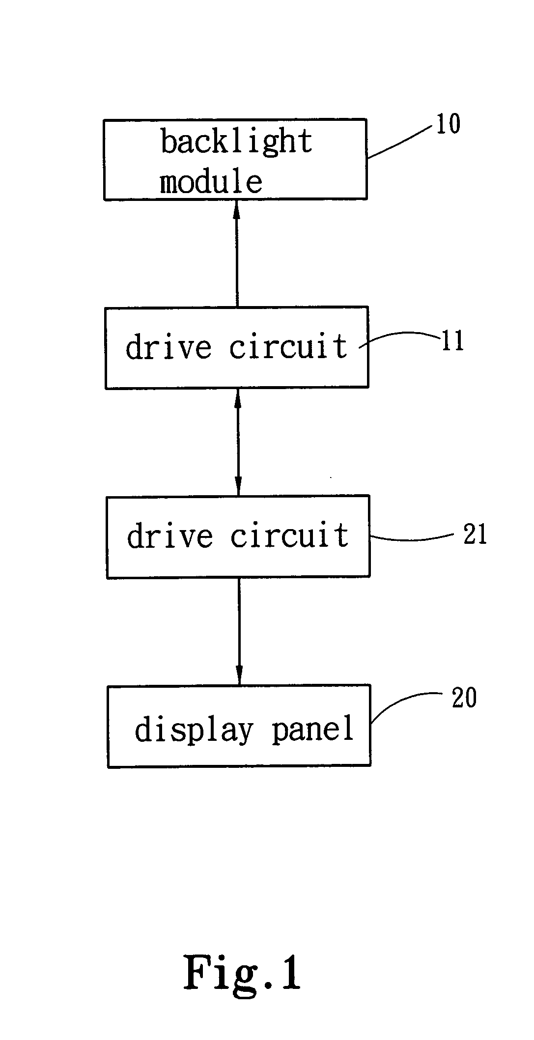
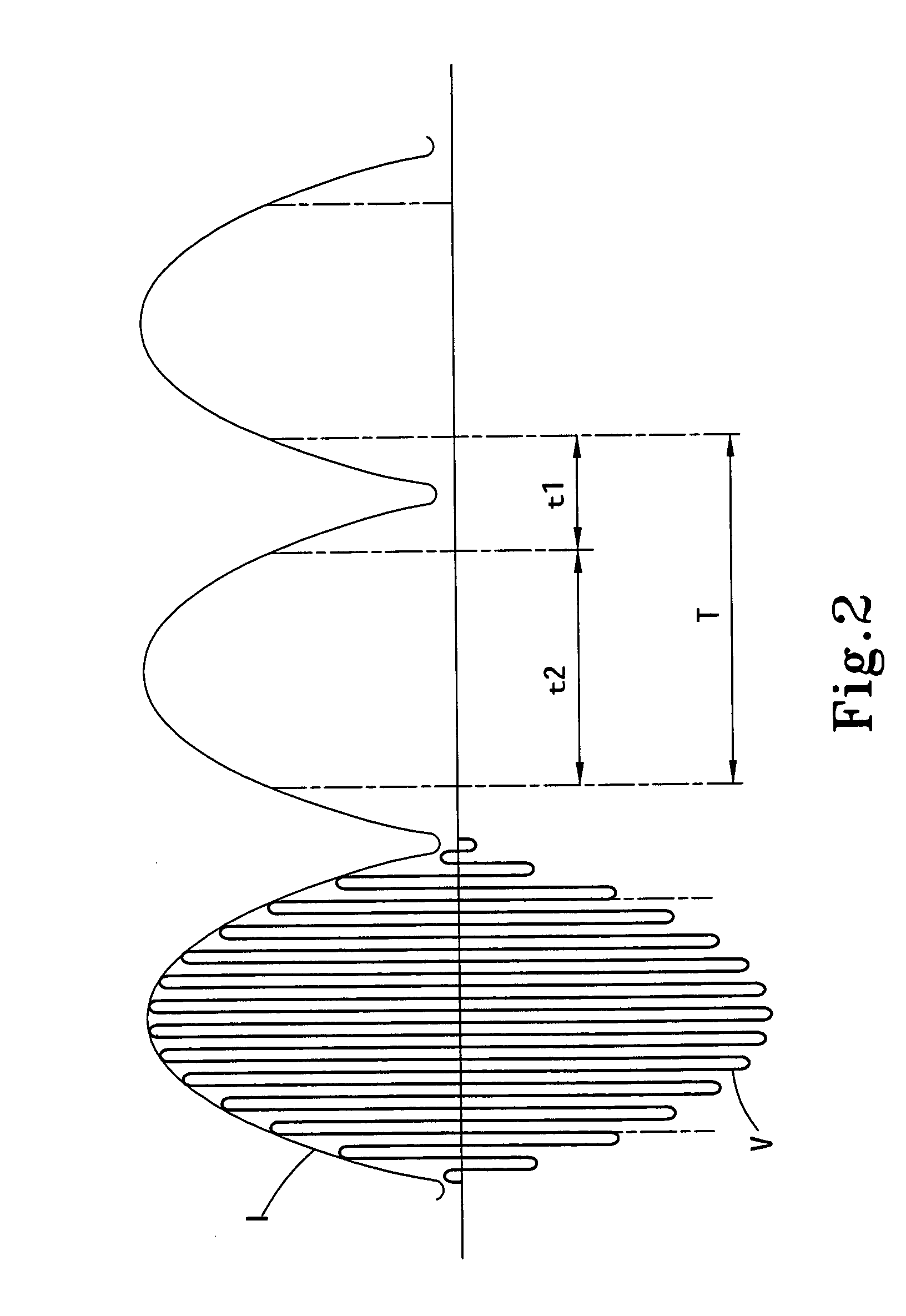
[0005] The primary objective of the present invention is to integrate the drive circuit of display panel and the drive circuit of backlight module to enable the image-display timing to mate the light-dark timing of the luminance variation so that the picture quality of the display panel can be promoted.

Problems solved by technology

When the current LCD panel performs image display, the color displayed by the current LCD panel is usually found not true enough.
In the conventional technology, the twist time of liquid crystal cell is larger than the response time of display panel; thus, when the display panel has changed the picture, the prior picture cannot renew in time; consequently, the trailing or residual image effects will appear, which influence the picture quality.
However, if the response time increases, the picture will be delayed, which is especially apt to happen when the consumer plays the motion-picture game or watches the movies.

Method used


Image

  • Drive device of display panel
  • Drive device of display panel
  • Drive device of display panel

Examples


Embodiment Construction

[0009] In cooperation with the attached drawings, the detailed description and the technical contents of the present invention are stated below.

[0010] Please refer to FIG. 1, a schematic function block diagram of the present invention as shown in FIG. 1, the present invention's drive device of display panel 20 comprises: a backlight module 10 and a drive circuit 11 of the backlight module 10, which are used to control the backlight source of the display panel 20, wherein the drive circuit 11 of the backlight module 10 has a means of creating a luminance variation cycle T to enable the backlight module 10 to represent light-dark timings t1 and t2 of luminance; and the display panel 20 and a drive circuit 21 of the display panel 20, which are used to control the image shift of the display panel 20, wherein the drive circuit 21 of the display panel 20 has a means of creating an image-display timing corresponding with the luminance variation cycle T to enable the image-display timing t...


PUM


Abstract

The present invention relates to a drive device of display panel, which integrates the drive circuit of the display panel and the drive circuit of the backlight module to enable the image-display timing of the display panel to mate the light-dark timing of the luminance variation cycle of the backlight module so that the picture quality of the display panel can be promoted.

Description

FIELD OF THE INVENTION [0001] The present invention relates to a drive device of display panel, particularly to a drive device, which applies to a display panel with backlight illumination and promotes the picture quality thereof. BACKGROUND OF THE INVENTION [0002] The liquid crystal display (LCD) panel, which utilizes the twist of liquid crystal molecules to display images, has become prevailing, and the quality of dynamic images becomes the determining factor when the consumer selects LCD panels with the audio / video function. [0003] When the current LCD panel performs image display, the color displayed by the current LCD panel is usually found not true enough. It primarily results from the influences of contrast level and response time. The response time herein refers to the span of time that a liquid crystal cell spends shifting from light to dark and then back to light, i.e. the time that a pixel spends shifting from white to black and then back to white. The response time is of...

Claims


Application Information

Patent Timeline
IPC IPC(8): G09G3/36
CPCG09G3/3406G09G2310/0237G09G2320/0261G09G2320/064
Inventor CHOU, CHIN-WENCHENG, YING-NANWU, KUANG-MING
Owner ZIPPY TECH
Learn More