Electronic control unit and method thereof

a technology of electronic control unit and control unit, which is applied in the direction of control unit, electric generator, electrical apparatus casing/cabinet/drawer details, etc., can solve the problems of harsher and harsher environmental conditions of engine control module, control unit, etc., and achieve the effect of reliable and inexpensive electronic control uni

Active Publication Date: 2006-08-03
HITACHI ASTEMO LTD
View PDF6 Cites 99 Cited by
  • Summary
  • Abstract
  • Description
  • Claims
  • Application Information

AI Technical Summary

Benefits of technology

[0015] It is an object of the present invention to provide an inexpensive and reliable resin-molded engine control unit where parts which should not be sealed with resin are mounted in resin-free regions.
[0027] If a configuration of the present invention is employed, parts which should not be sealed with resin can be mounted in resin-free regions. This makes it possible to provide an inexpensive and reliable electronic control unit.

Problems solved by technology

Recently, the thermal environments of engine control modules (hereinafter, denoted as “engine control units”) used in automobiles, ships, agricultural machines, engineering machines and electric generators are getting harsher and harsher.
However, on-engine mount units are used in a still harsher thermal environment.
Engine control units for installation in engine compartments cannot operate at temperatures higher than 100° C. and therefore can not cope with such an environment.
Although there are engine control units which employ a high heat radiation structure comprising a ceramic board and bare chips, this structure is expensive as compared to the conventional structure.
The conventional technology of Japanese Patent Laid-Open No. 2004-111435, which encapsulates all electronic parts by resin molding, has various problems.
For example, the internal electrolytic solution of an electrolytic capacitor used in an engine control unit usually causes a small amount of leakage to the outside due to gasification.
Therefore, if the electrolytic capacitor is sealed with resin, the gasified electrolyte solution accumulates near an electrode of the electrolytic capacitor and may result in causing a short circuit.
Although an electrolytic capacitor is usually provided with an explosion-protection valve to release the gas pressure, the gas pressure may rise since this function is disabled if the electrolytic capacitor is sealed with resin.
Therefore, using this conventional technology with electrolytic capacitors is not practical.
Although ceramic capacitors, tantalum capacitors and like can be used as substitutes, they are expensive and have a disadvantage in terms of cost.
Therefore, this requirement can not be met if the control unit is encapsulated simply by resin molding.
In addition, large coils used in engine control units are likely to change in properties if they are sealed with resin.
Therefore, it is not preferable to seal coils with resin in resin-molded engine control units.
However, if the electronic unit is encapsulated by resin molding, it is not possible to probe or visually inspect the internal circuit and electronic elements after the occurrence of a trouble in the electronic circuit.
This makes it difficult to determine the causes of abnormalities of the system.
In the case of Japanese Patent Laid-Open No. 1996-70066 which discloses a structure where a cavity is provided on only one side of the circuit board, it is not possible to contain large electronic parts such as pin insertion type ones although this is effective to semiconductor and other small parts.

Method used


Image

  • Electronic control unit and method thereof
  • Electronic control unit and method thereof
  • Electronic control unit and method thereof

Examples


embodiment 1

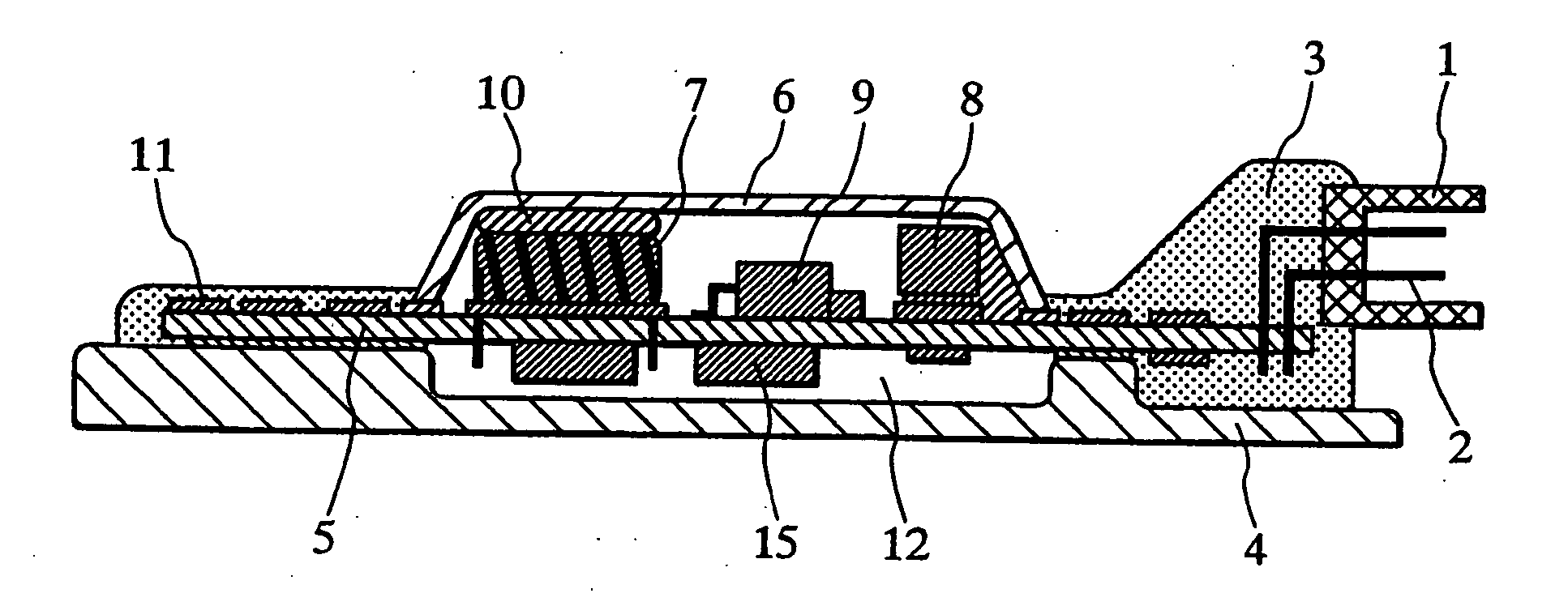
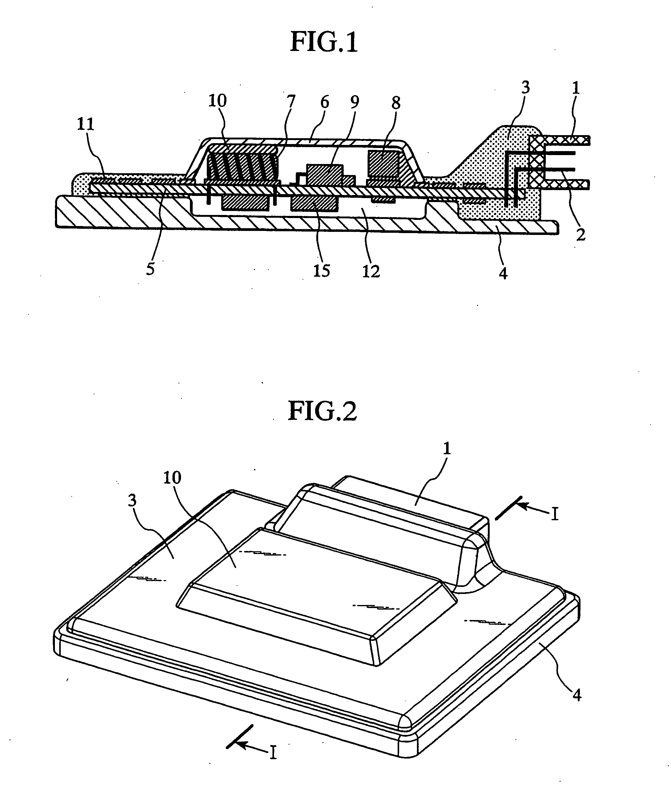
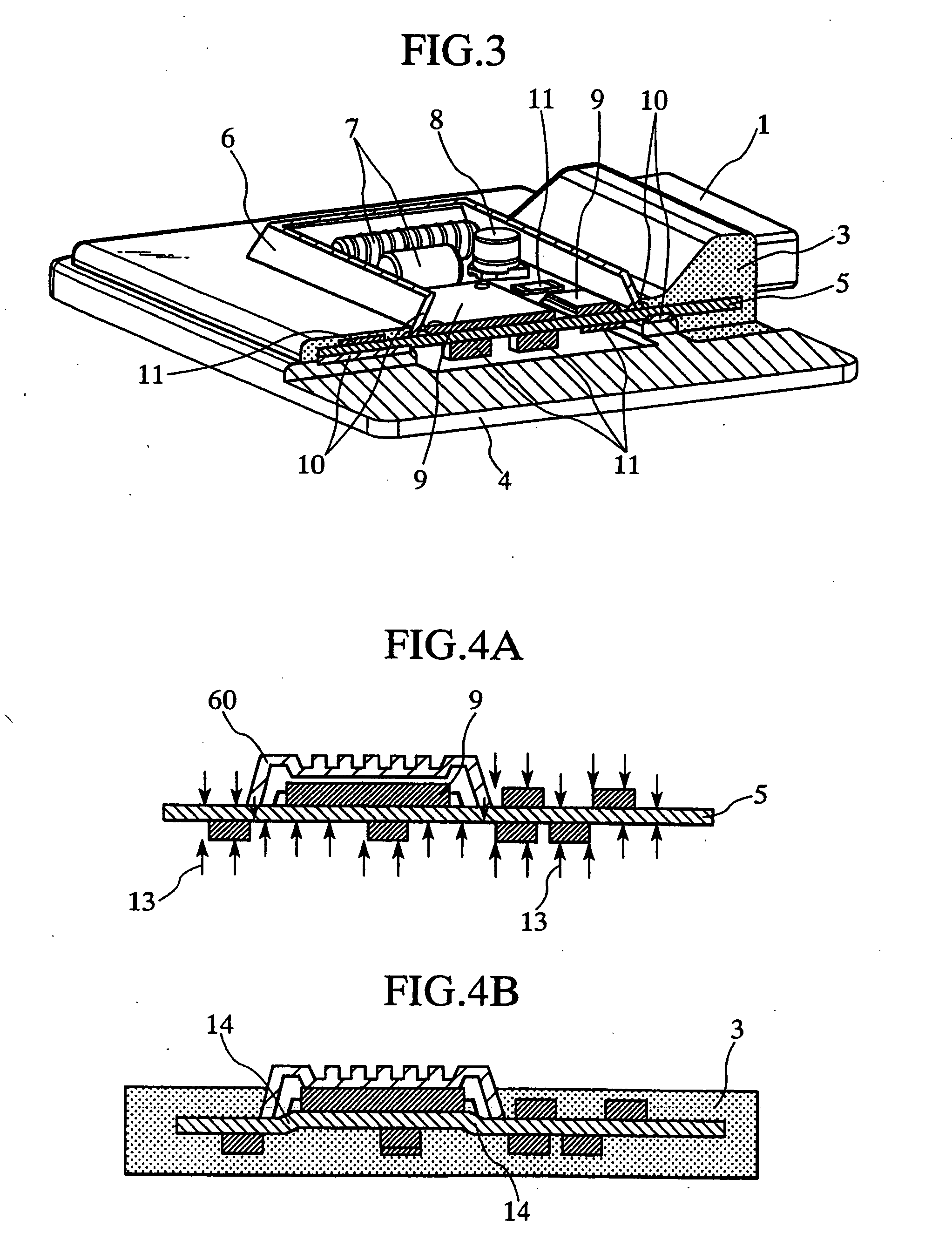
[0051]FIG. 1 is a cross sectional view of an engine control unit, a first embodiment of the present invention. FIG. 2 is a perspective view showing the external appearance of the present engine control unit embodiment. FIG. 3 is a perspective view showing the internal structure of the engine control unit with a cover opened.

[0052] The cross sectional view of FIG. 1 shows a section cut along I-I in FIG. 2. 11 and 15 denote surface mount type small parts. For example, they are a resistor, capacitor, coil, crystal, diode, IC, FET, transistor, etc. 7 is a pin insertion type electronic part, typically, a coil which is difficult to seal with resin. Instead of a coil, the pin insertion type electronic part 7 may also be a resistor, capacitor, crystal, diode, IC, FET, transistor or the like. 8 is a surface mount type large electronic part, typically, an electrolytic capacitor which is difficult to seal with resin. Instead of an electrolytic capacitor, the surface mount type large electroni...

embodiment 2

[0074]FIG. 6 shows a cross sectional view of an engine control unit according to a second embodiment of the present invention. Components that are identical to the corresponding ones in the first embodiment are given the same reference numeral in FIG. 6 as in FIG. 1, and their description is omitted.

[0075] In the present embodiment, a cover 6b is formed on the bottom side of the board 5 whereas the first embodiment has the base 4 formed thereon. Covers 6a and 6b are formed respectively on the top and bottom sides of the board before encapsulation by resin molding. Therefore, since the molding pressure does not act on the board area provided with the covers 6a and 6b during resin molding, it is possible to carry out resin molding without warping the board 5. In addition, since the base 4 is not necessary in the present invention, it is possible to provide a lower cost engine control unit than the first embodiment. Furthermore, because both covers 6a and 6b can be opened when trouble...

embodiment 3

[0079]FIG. 7 is a cross sectional view of an engine control unit according to a third embodiment of the present invention. Components that are identical to those in the first embodiment are given the same reference numeral in FIG. 7 as in FIG. 1, and their description is omitted.

[0080] In the present embodiment, a microprocessor 9 to control an engine and a coil 7 and electrolytic capacitor 8 which produce noise and heat are capped by separate covers 6c and 6d. If some control problem occurs, the microprocessor 9 must be analyzed to locate the cause. Due to their properties, the coil 7 and electrolytic capacitor 8 are difficult to seal with resin. Therefore, the microprocessor 9, coil 7 and electrolytic capacitor 8 must be mounted in a region which is not filled with the resin 3.

[0081] However, the microprocessor 9 is vulnerable to high temperature as compared to other passive parts and FETs. In addition, protection from noise is critical to prevent its malfunction. Therefore, the...


PUM


Abstract

In resin-molded engine control unit, a coil, an electrolytic capacitor, a microprocessor, electronic parts and a connector terminal are mounted on a board. Inside a cover fixed on the board, a resin-free region is formed. The coil, the electrolytic capacitor and the microprocessor, which should not be sealed with resin, are mounted in the resin-free region, while the board and the electronic parts which are not capped by the cover are sealed with a resin.

Description

BACKGROUND OF THE INVENTION [0001] The present invention relates to the structures of module units having electronic parts and waterproof connectors mounted on circuit boards and encapsulated therein by resin molding. In particular, the invention relates to a structure suitable for engine control units and other electronic control units installed in automobiles, ships, agricultural machines, engineering machines, electric generators, etc. [0002] Recently, the thermal environments of engine control modules (hereinafter, denoted as “engine control units”) used in automobiles, ships, agricultural machines, engineering machines and electric generators are getting harsher and harsher. [0003] That is, the situation is: (1) while they were conventionally installed in cabins, installation in engine compartments and on-engine mount are becoming popular, exposing engine control units to higher temperatures; (2) the amounts of heat generated by engine control units are increasing due to the in...

Claims


Application Information

Patent Timeline
Patent Type & Authority Applications(United States)
IPC IPC(8): H05K5/02
CPCB29C45/14377B29C45/14655B60R16/0239H01L21/565H01L25/165H05K1/189H05K3/0061H05K3/284H05K5/0034H05K2201/09745H05K2201/10189H05K2201/10371H05K2201/1056H05K2203/1316H05K2203/1572H01L2924/0002H01L2924/00
Inventor KADOYA, KIYOOMISASAKI, MASAHIROMAYUZUMI, TAKUYA
Owner HITACHI ASTEMO LTD
Why Eureka
Try Eureka