Hinge structure of folding type mobile communication device

a mobile communication device and hinge structure technology, applied in the direction of electrical equipment, substation equipment, interconnection arrangements, etc., can solve the problem of insufficient mechanical strength of the hinge portion, and achieve the effect of improving outer appearance and mechanical strength

Inactive Publication Date: 2006-08-03
NEC CORP
View PDF6 Cites 8 Cited by
  • Summary
  • Abstract
  • Description
  • Claims
  • Application Information

AI Technical Summary

Benefits of technology

The objective of this patent is to create a mobile phone that has a stronger and more attractive hinge mechanism. This will improve its overall performance and make it easier for users to use. Additionally, the patent provides a specific hinge design that can be utilized for such devices.

Problems solved by technology

The technical problem addressed in this patent is to improve the design of the hinge structure in folding type mobile communication devices by eliminating the need for insertion holes and hinge caps, and increasing the mechanical strength of the hinge portion.

Method used


Image

  • Hinge structure of folding type mobile communication device
  • Hinge structure of folding type mobile communication device
  • Hinge structure of folding type mobile communication device

Examples


Embodiment Construction

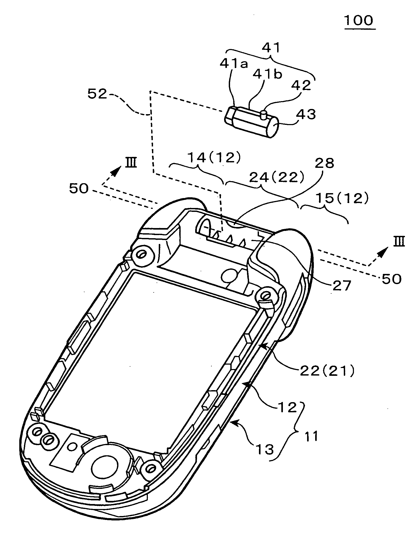
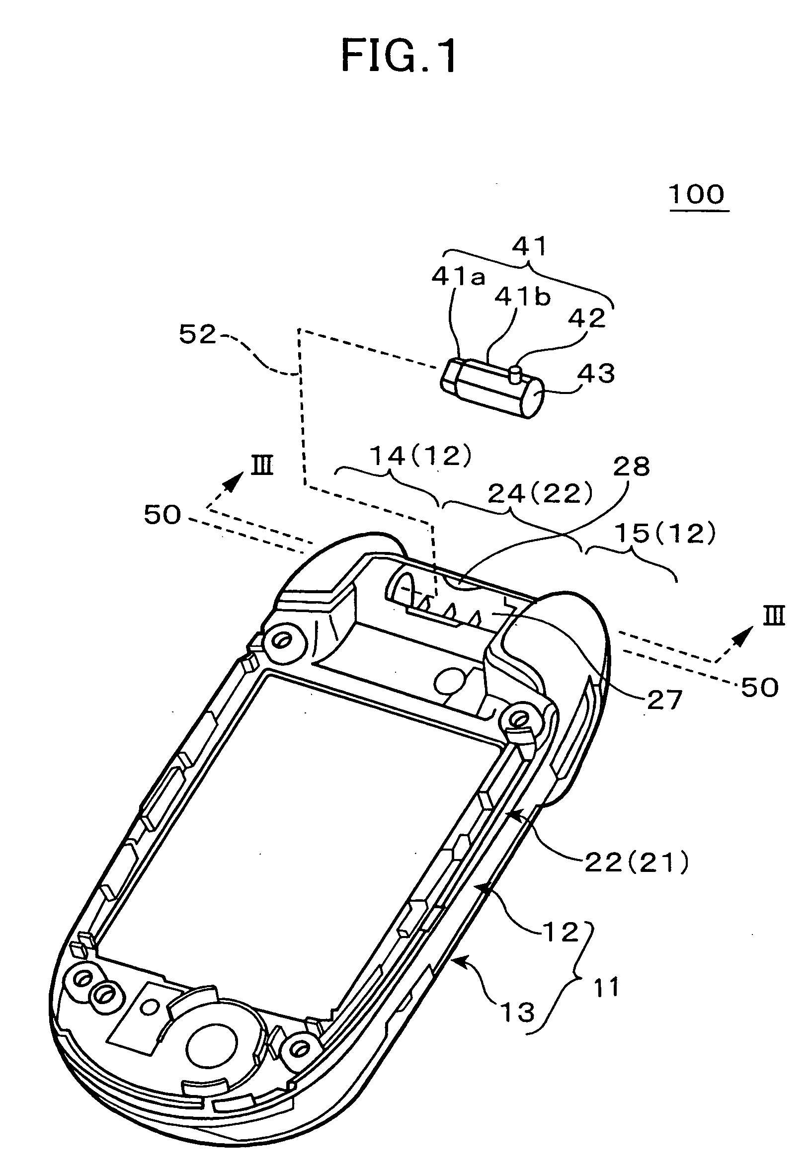
[0028] Now, an embodiment of the present invention will be described in detail with reference to the drawings. FIG. 1 shows the folding type mobile communication device according to one embodiment of the present invention with an outer casing of an upper case removed and with a pivotal shaft of a hinge structure exploded.

[0029] The mobile communication device 100 comprises a lower case 11 for housing various operation keys, a microphone, an antenna and the like and an upper case 21 for housing a liquid crystal display device, a speaker and the like. By the use of a pivotal shaft 41 to be inserted into a hinge portion that is formed at one edge portions of the lower case 11 and the upper case 21 and a dummy pivotal shaft 44, the lower case 11 and the upper case 21 can be pivoted between a folded position in which the lower case 11 and the upper case 21 are in contact with each other and an unfolded position in which the lower case 11 and the upper case 21 are unfolded to substantial...


PUM


Abstract

Disclosed are a mobile communication device and a hinge structure therefor with improved mechanical strength and outer appearance. The mobile communication device 100 comprises the lower case 11 and the upper case 21 mutually coupled to each other by way of the hinge structure so that the two cases 11, 21 are pivoted to take either the folded position or the unfolded position. The hinge structure comprises: the bearing structure comprising the first bearing portion 16 formed in the first case 11 with open at one end and closed at the other end and the second bearing portion 25, 26, 27 formed in the second case 21 with open at both ends, wherein one end of the second bearing portion 25, 26, 27 is disposed adjacent to one end of the first bearing portion 16 in the axial direction; the pivotal shaft 41 comprising the first shaft portion 41b pivotally mounted on the first bearing portion 16 and supported so as to move in the axial direction and the second shaft portion 41a pivotally mounted on the second bearing portion 25, 26, 27 and supported so as to move in the axial direction, wherein the first and second shaft portions are pivotally coupled; and the opening 28 formed in the upper case 21 at a location adjacent to the bearing structure in the axial direction so that the pivotal shaft 41 is permitted to pass.

Description


Claims


Application Information

Patent Timeline
Owner NEC CORP
Why Eureka
Try Eureka