Multilayer secondary battery and method of making same

Active Publication Date: 2006-08-03
NEC ENERGY DEVICES LTD
View PDF5 Cites 63 Cited by
  • Summary
  • Abstract
  • Description
  • Claims
  • Application Information

AI Technical Summary

Benefits of technology

[0021] A primary object of the invention is to provide a lithium ion secondary battery which, even when positive and negative electrodes differing in electrode area are stacked together as is the case with an existing lithium ion battery wherein a multilayer structure comprising flat sheet-form positive and negative elect

Problems solved by technology

When, in manufacturing an electrode element by stacking the positive electrode and the negative electrode together via the separator, the multilayer electrode element is contained in an outer container such as a metal can or sealed up with an outer casing member having flexibility, it is found that there is a misalignment because the flat sheet-form positive electrode 2, the flat sheet-form negative electrode 3 and the separator 4 are each of independent structure, offering problems that internal short circuits occur upon partial direct contact of the positive electrode 2 with the negative electrode 3, or a misalignment between the positive electrode 2 and the negative electrode 3 fails to give any desired properties in terms of the charge/discharge capacity, etc. of the battery.
As the size of the separator is increased to get around internal short circuits even upon some electrode misalignment, the size of the outer container grows large, resulting in

Method used


Image

  • Multilayer secondary battery and method of making same
  • Multilayer secondary battery and method of making same
  • Multilayer secondary battery and method of making same

Examples


Embodiment Construction

[0055] According to the invention, it is possible to obtain a multilayer secondary battery of high reliability which, like an existing lithium ion battery, is free from any mutual electrode misalignment even upon stacking of positive and negative electrodes differing in the areas of positive and negative electrode active substance layers, and free from any short circuit between the positive electrode and the negative electrode as well.

[0056] The multilayer secondary battery of the invention is now explained with reference to the drawings.

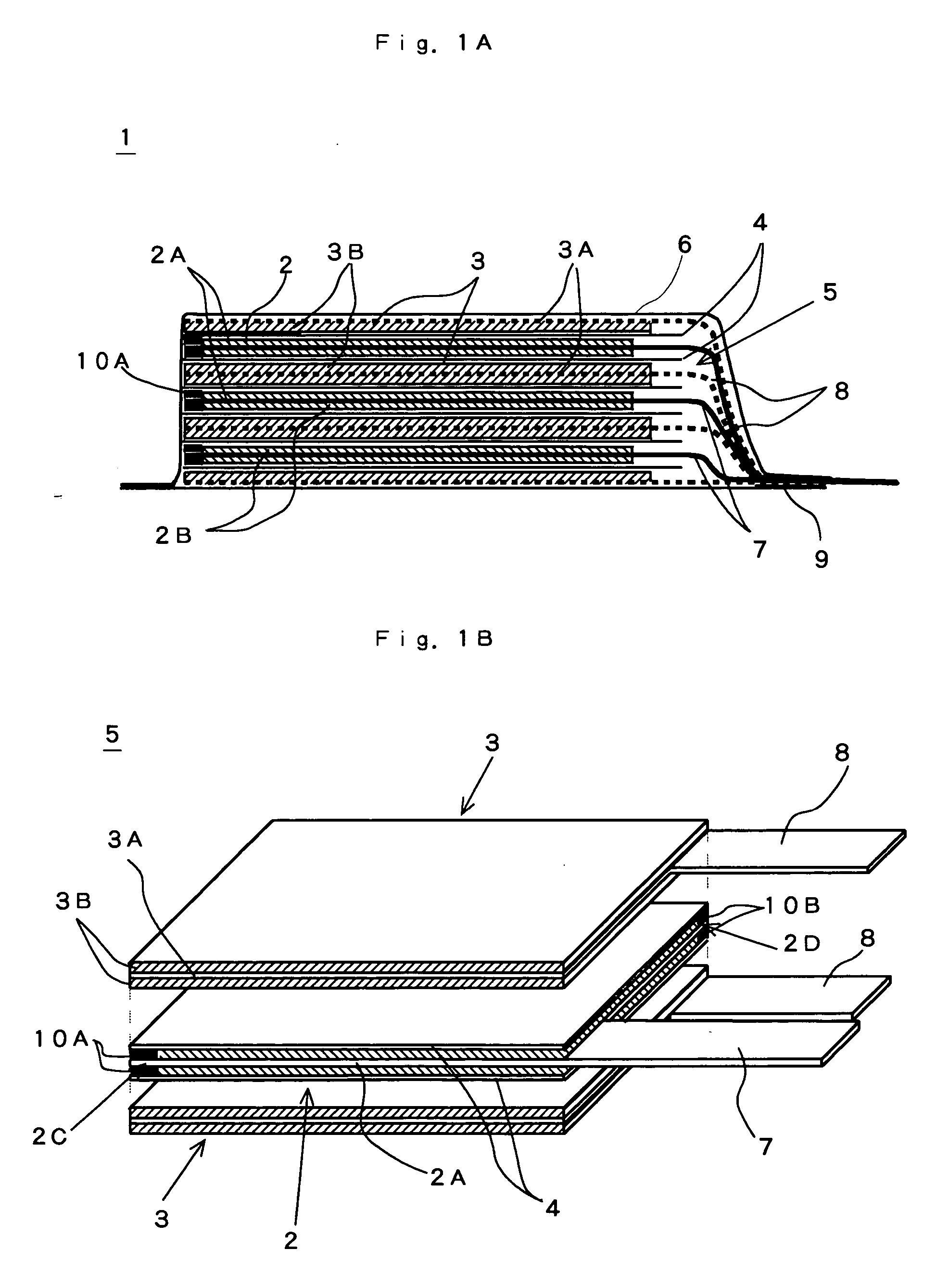
[0057]FIG. 1A is illustrative in section of the multilayer secondary battery according to the invention.

[0058]FIG. 1B is illustrative in perspective of a battery element in which some electrodes in the multilayer secondary battery according to the invention are stacked together.

[0059] A multilayer secondary battery 1 comprises an electrode element 5 sealed up with an outer casing member 6, in which element a plurality of flat sheet-form positive...


PUM


Abstract

The invention provides a multilayer secondary battery in which a positive electrode having a positive electrode active substance layer formed on a flat sheet-form collector and a negative electrode having a negative electrode active substance layer formed on a flat sheet-form collector are stacked together in opposite relation via a separator. The positive electrode active substance layer differs in area from the negative electrode active substance layer. Active substance-free portions with no active substance layer coated on them are formed on at least adjoining two sides of the outer periphery of a collector of a smaller area electrode having a smaller active substance layer area. The surface of the collectors at the active substance-free portions is covered with an insulating substance layer. The end face of the insulating substance layer that faces away from a side contiguous to an active substance layer and the end face of a larger area electrode having a larger active substance layer area are located and stacked together on the same plane that intersects vertically an electrode plane.

Description

CROSS-REFERENCE TO RELATED APPLICATIONS [0001] This application is based upon and claims the benefit of priority from prior Japanese Patent Application No. 2005-21458, filed on Jan. 28, 2005, the entire contents of which are incorporated herein by reference. BACKGROUND [0002] 1. Technical Field [0003] The present invention relates generally to a multilayer secondary battery with a plurality of flat-form electrodes stacked together via a separator, and more particularly to a multilayer secondary battery wherein a positive electrode and a negative electrode differing in electrode area are stacked together via a separator and a method of making the same. [0004] The invention is also concerned with a lithium ion secondary battery with a positive electrode smaller in size than a negative electrode and a method of making the same. [0005] 2. Related Art [0006] Lithium ion batteries known until now are broken down into a wound-up type battery comprising an outer container containing a wound...

Claims


Application Information

Patent Timeline
IPC IPC(8): H01M6/24
CPCH01M2/1673H01M2/34H01M10/0436H01M10/0525H01M2010/4292Y02E60/10H01M50/46
Inventor MIMURA, KAZUYA
Owner NEC ENERGY DEVICES LTD
Why Eureka
Try Eureka