
Marine vessel propulsion structure and marine vessel driving apparatus

a propulsion structure and driving apparatus technology, applied in the direction of marine propulsion, vessel parts, vessel construction, etc., can solve the problems of increased maintenance cost of marine vessels, poor fuel economy, and large consumption of fuel, so as to achieve superior structure, prevent fuel consumption, and maintain good balance of marine vessels.

Inactive Publication Date: 2006-08-03
ARK SYST CORP
View PDF8 Cites 47 Cited by
  • Summary
  • Abstract
  • Description
  • Claims
  • Application Information

AI Technical Summary

Benefits of technology

[0010] It is therefore an object of the present invention to provide a marine vessel propulsion structure and marine vessel driving apparatus which facilitates steering of a marine vessel such as the turning-around of the marine vessel, the swinging-around of the marine vessel, etc., ensures keeping of a balance of the marine vessel during the travel of the marine vessel, ensures good fuel economy for driving the marine vessel, and facilitates saving of maintenance cost of the marine vessel.
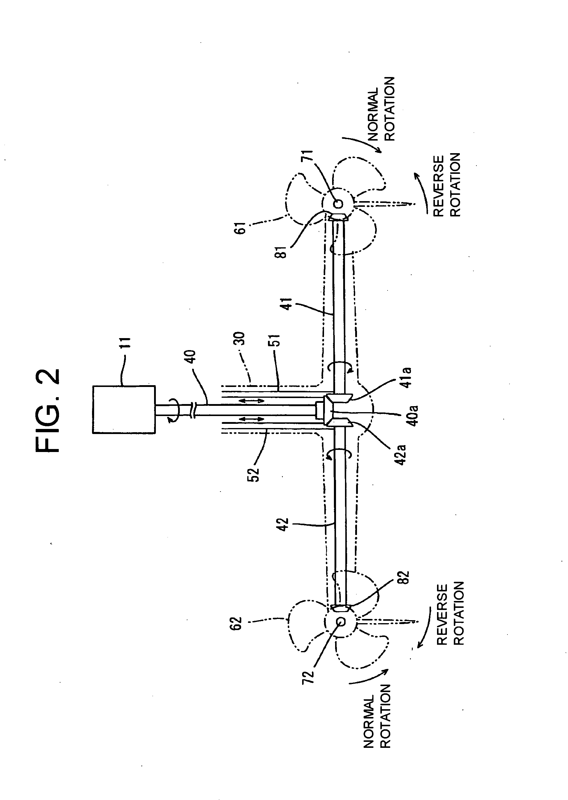
[0023] As discussed above, according to the present invention, the power transmitted to the single main drive shaft is transmitted to the separate propeller shafts to thereby cause the propellers to be rotated, the rotation situations of the respective propellers are controlled independently from each other, so that the number of the engine installed may be one, the maneuverability and balance of the marine vessel can be improved, the cost of fuel consumed for driving the marine vessel can be reduced and the maintenance cost of the marine vessel can be also reduced.

Problems solved by technology

In a case where, like the conventional marine vessel, a marine vessel is provided with two outboard drives or the like, there are raised problems that much fuel is consumed for driving two engines and fuel economy is therefore poor, a poor balance of the marine vessel is offered due to an increased weight of the rear portion of the marine vessel, and maintenance cost of the marine vessel is increased.
Furthermore, in a marine vessel employing the structure in which the plurality of propellers are mounted on the single propeller shaft like the above-mentioned prior art structure, turning-around of the marine vessel is performed with resort to a rudder, so that it is hard to delicately steer the marine vessel.

Method used


Image

  • Marine vessel propulsion structure and marine vessel driving apparatus
  • Marine vessel propulsion structure and marine vessel driving apparatus
  • Marine vessel propulsion structure and marine vessel driving apparatus

Examples


first embodiment

(1) First Embodiment

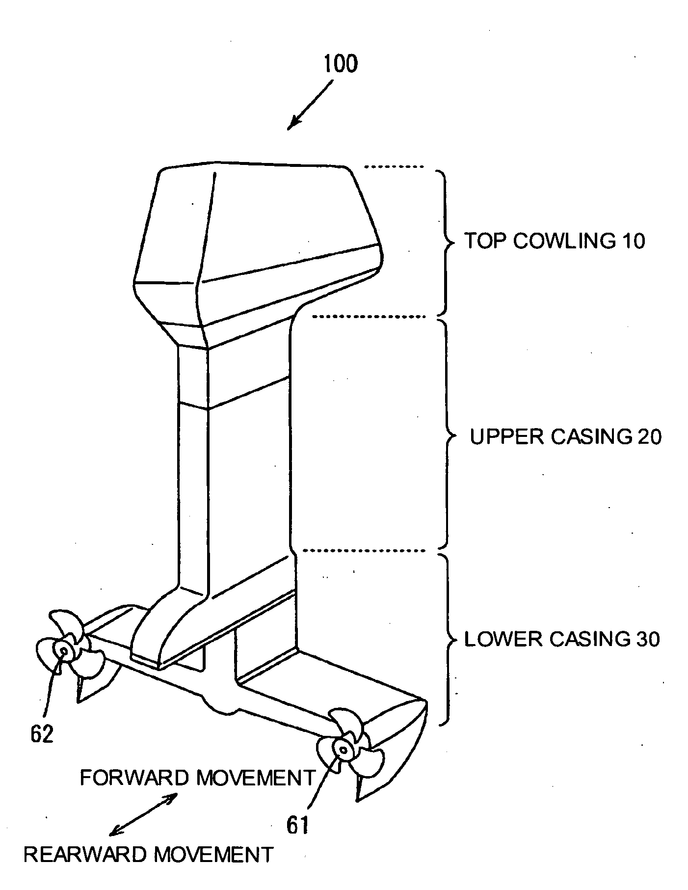
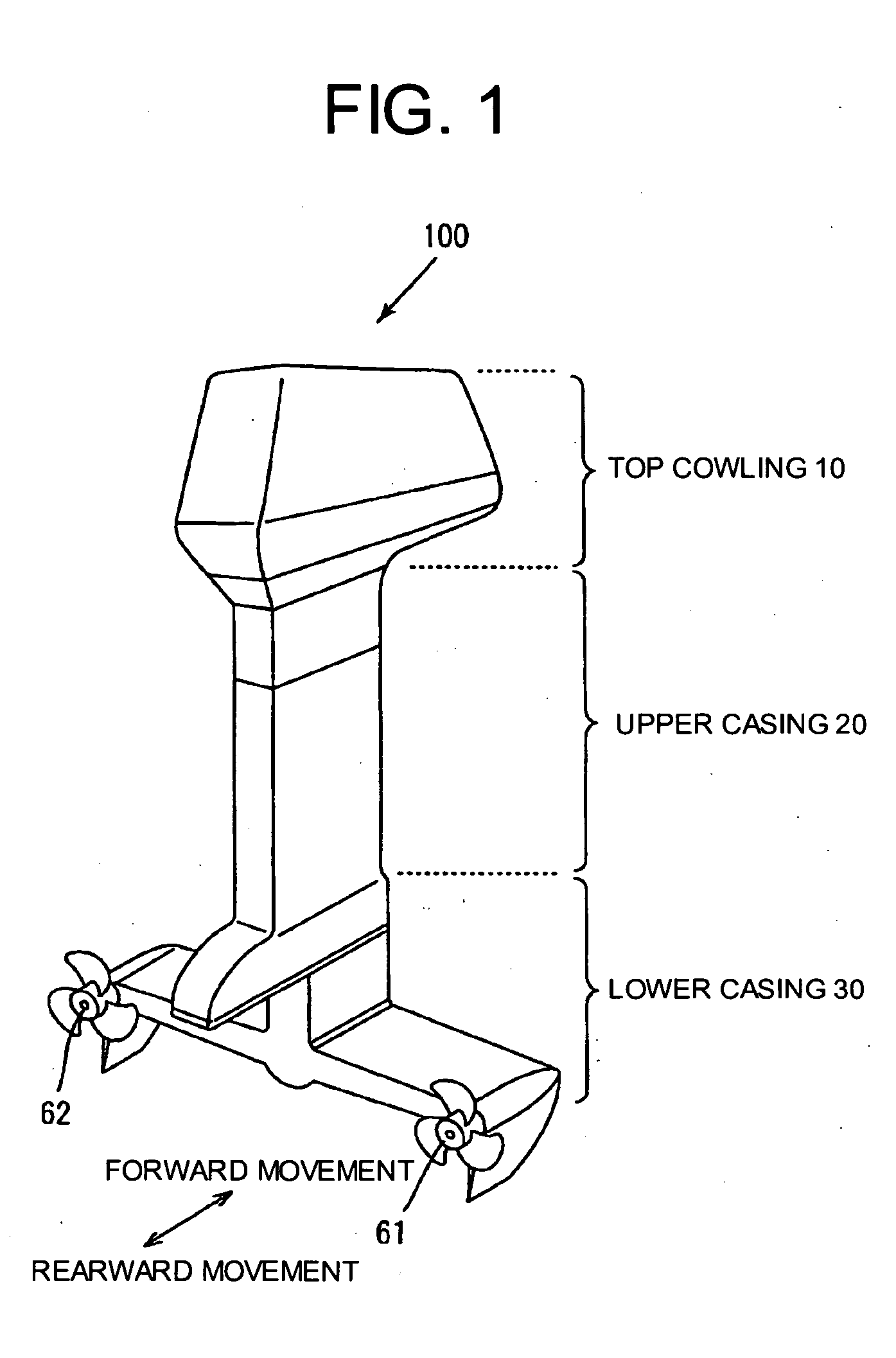
[0035]FIG. 1 is a schematic perspective view illustrating an appearance of an outboard drive corresponding to a marine vessel driving apparatus according to the present invention.

[0036] The outboard drive 100 is arranged at a rear portion of a marine vessel such as a boat or the like so as to be well-balanced by causing a vertical center line of the outboard drive to be aligned with a center location of a longitudinal direction of the marine vessel. The traveling of the marine vessel on the water can be realized by rotation of propellers. The outboard drive includes a top cowling 10, an upper casing 20, a lower casing 30, and two right and left propellers 61, 62 exposed to the exterior on the both sides of a lower part of the lower casing 30, which are arranged in order from substantially above.

[0037] In an interior of the top cowling 10 of the outboard drive 100, a power unit including a single engine 11 (see FIG. 2), a starter motor, and like is housed. Moreo...

second embodiment

(2) Second Embodiment

[0070]FIG. 6 is a schematic view of an inboard-outboard drive corresponding to a marine vessel driving apparatus of the present invention, in which a part of the inboard-outboard drive is illustrated in perspective.

[0071] Unlike the above-mentioned outboard drive 100, the inboard-outboard drive 200 has an engine 230 installed in a predetermined location of an interior of a marine vessel 300 and a drive unit that includes propellers and arranged outboard. Moreover, like the outboard drive 100, the inboard-outboard drive 200 is arranged at a rear portion of the marine vessel so as to be well-balanced by causing a vertical center line of the inboard-outboard drive to be aligned with a center location of a longitudinal direction of the marine vessel.

[0072] The second embodiment is different from the first embodiment in a structure of a main drive shaft.

[0073] The main drive shaft of the inboard-outboard drive 200 comprises a first main drive shaft element 210 tha...


PUM


Abstract

In an outboard drive or an inboard-outboard drive, power generated by a single engine is transmitted in left and right directions from a main drive shaft, thereby finally causing left and right propellers to be rotated, the left and right propellers being arranged about the main drive shaft so as to be spaced apart from the main drive shaft at approximately equal distances from the main drive shaft and facing a travel direction of a marine vessel, the outboard drive or inboard-outboard drive being provided with left and right shift cam assemblies for causing rotation situations of the propellers to be controlled dependently from each other, the rotation situations including normal rotation, reverse rotation and non-rotation situations of the propellers.

Description

BACKGROUND OF THE INVENTION [0001] 1. Field of the Invention [0002] The present invention relates to a marine vessel propulsion structure and marine vessel driving apparatus which causes a marine vessel to be propelled using a plurality of propellers. [0003] 2. Description of the Related Art [0004] Hitherto, in order to facilitate improving of maneuverability of a marine vessel such as a boat or the like upon steering of the marine vessel, two so-called outboard drives or inboard-outboard drives which are each provided with a single engine and propellers driven by the single engine are installed at predetermined locations of a rear portion of the marine vessel. [0005] Moreover, there is known a tandem propeller mounting structure in which two forward and rearward propellers constituting a tandem propeller system are mounted on a single propeller shaft (for example, Japanese Patent Application Laid-Open No. Hei. 5-58389). [0006] Also, there is known a structure in which a plurality o...

Claims


Application Information

Patent Timeline
IPC IPC(8): B63H20/14B63H23/00
CPCB63H5/08B63H20/00B63H20/12B63H20/14B63H20/20B63H23/04B63H23/08B63H25/42B63H2020/005
Inventor KAWAMOTO, KOJI
Owner ARK SYST CORP
Learn More