Torque-vectoring defferential

a torque vector and differential technology, applied in mechanical equipment, transportation and packaging, gearing, etc., can solve the problems of reducing the handling of vehicles, both driving wheels to the same speed, and the characteristic of limited-slip differentials

Inactive Publication Date: 2006-08-03
THE TIMKEN CO
View PDF6 Cites 26 Cited by
  • Summary
  • Abstract
  • Description
  • Claims
  • Application Information

AI Technical Summary

Problems solved by technology

To be sure, limited-slip differentials exist, but that type of differential tends to bring both drive wheels to the same velocity.
Where tr

Method used


Image

  • Torque-vectoring defferential
  • Torque-vectoring defferential
  • Torque-vectoring defferential

Examples


Embodiment Construction

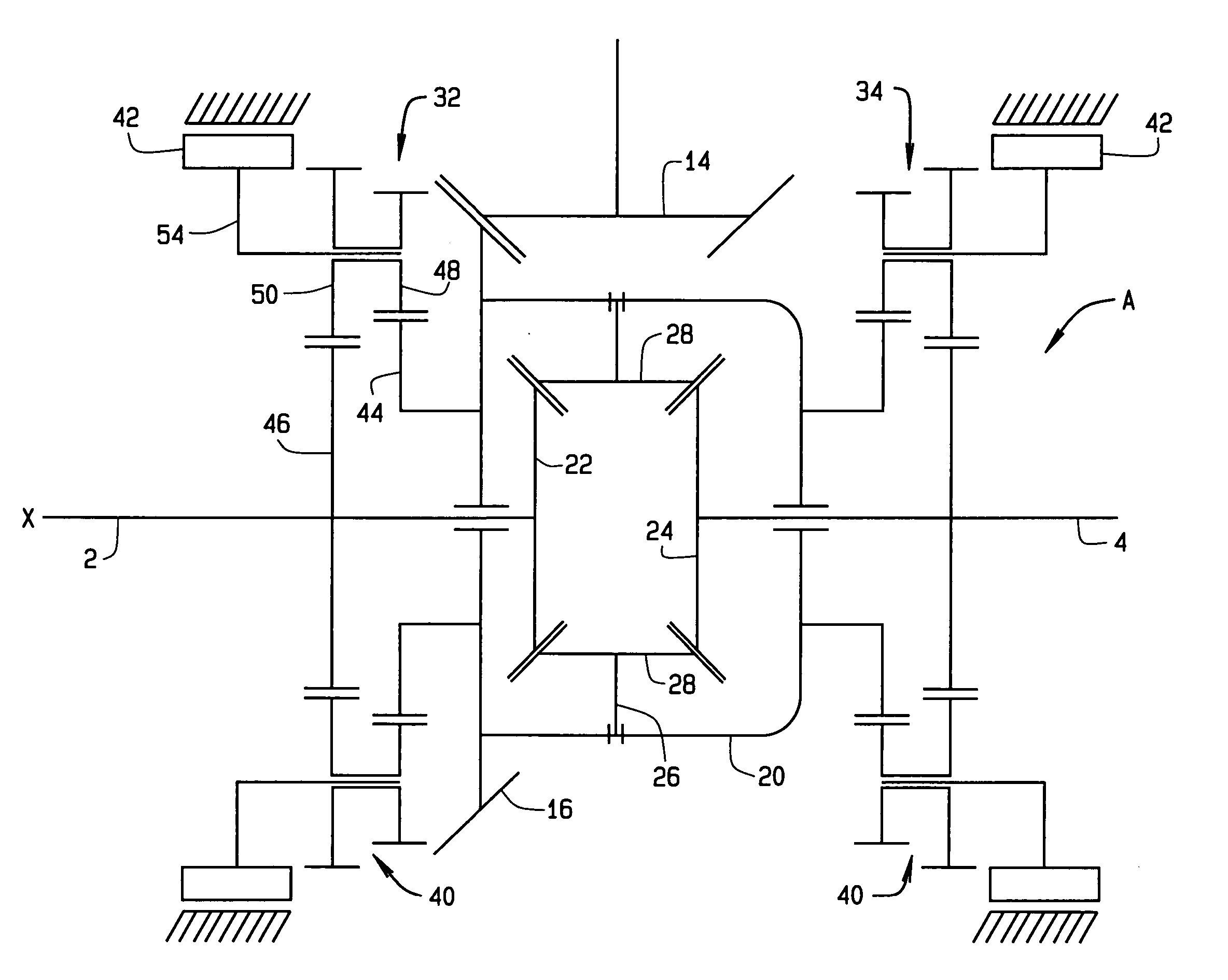
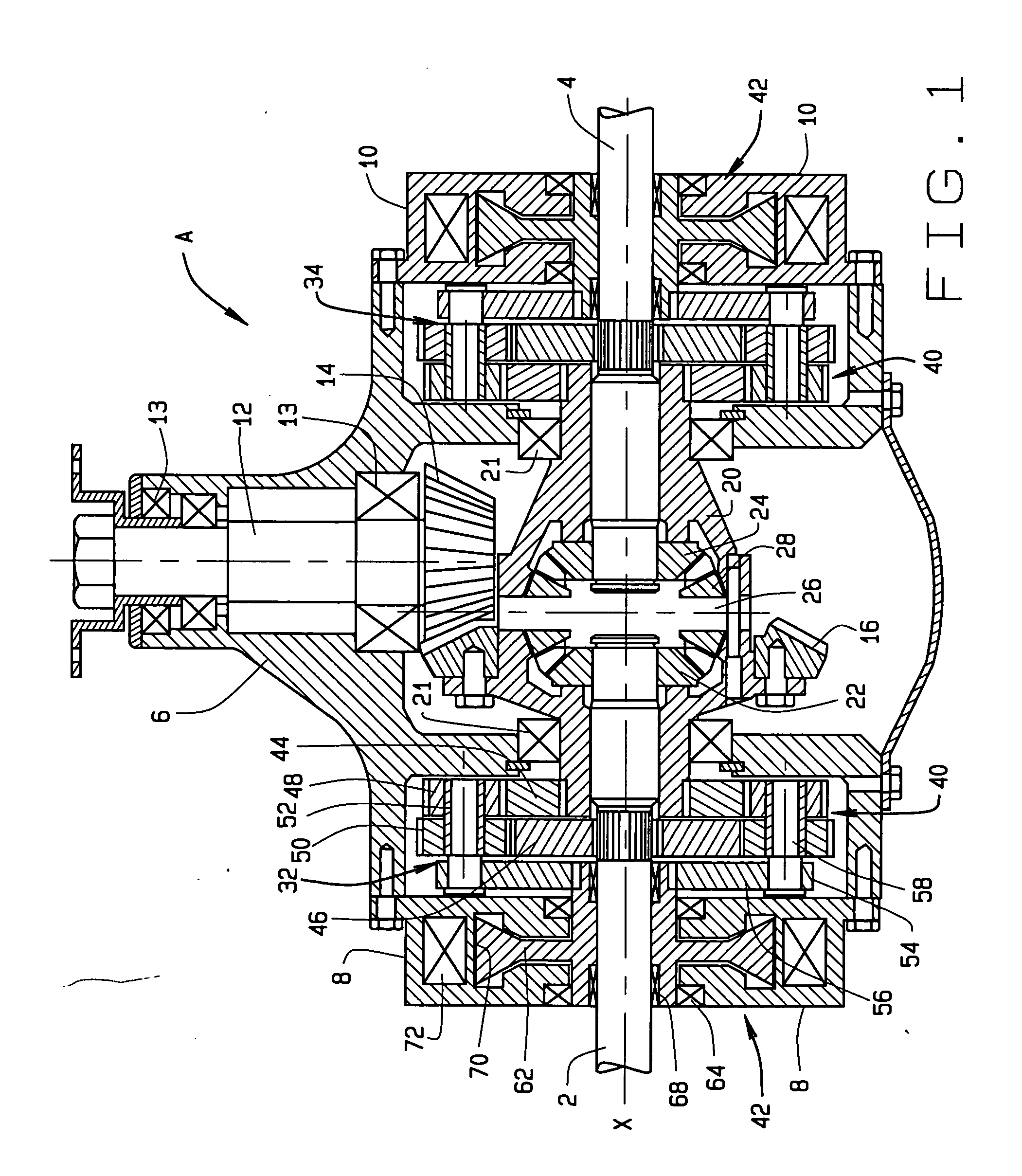
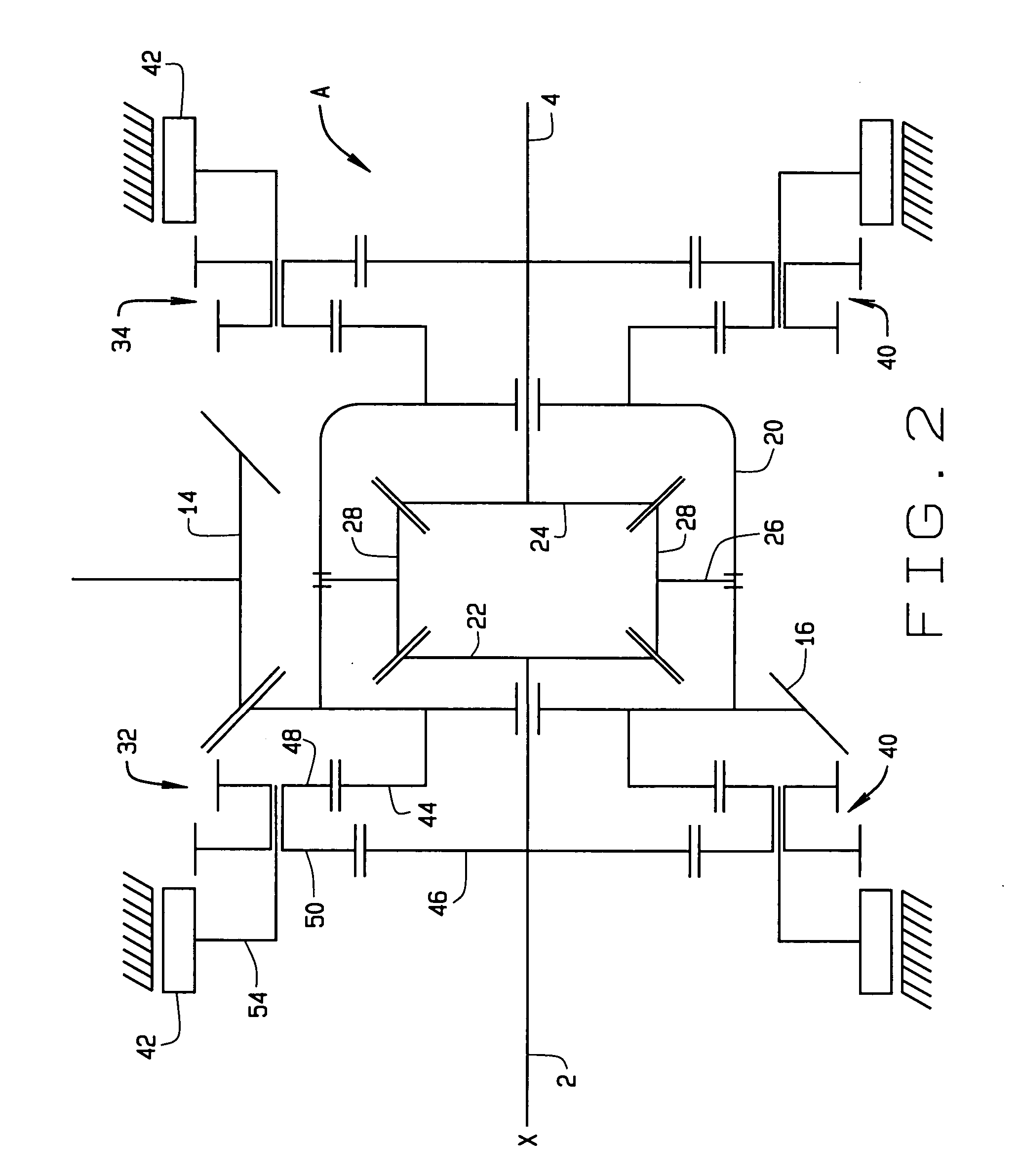
[0010] Referring now to the drawings, a differential A (FIG. 1) for an automotive vehicle distributes torque produced by the engine of the vehicle to two axle shafts 2 and 4 which rotate about a major axis X and are coupled to road wheels located, respectively, at the left and right sides of the vehicle. The differential A has the capacity to selectively vector the torque delivered to the two shafts 2 and 4, so that one of the shafts 2 or 4 may transfer greater torque than the other. This enhances control of the vehicle.

[0011] The differential A includes a housing 6 which contains the working components of the device and includes a left and right end closures 8 and 10. The left axle shaft 2 projects out of the left closure 8, whereas the right axle shaft 4 projects out of the right closure 10.

[0012] The differential A can function as a conventional differential and often does. To this end, it has (FIG. 1) a pinion shaft 12 that rotates in the housing 6 on bearings 13. The pinion s...


PUM


Abstract

A differential for selectively vectoring torque to left and right axle shafts that rotate about an axis includes a cage that rotates about the axis as a consequence of torque applied to it. The cage contains gearing that transfers the torque to the axle shafts while accommodating for variances in angular velocity between the axle shafts. In addition, the differential has left and right torque diverters for the left and right axle shafts, with each torque diverter including a planetary set connected between the cage and its axle shaft and a brake which imparts a reactive torque to its planetary set so that the planetary set diverts torque from the cage through the planetary set to its axle shaft. The brakes, which are preferably magnetic particle brakes, control the torque delivered to the axle shafts, so the differential has the capacity to vector the torque applied to its cage.

Description

CROSS-REFERENCE TO RELATED APPLICATIONS [0001] Not applicable. STATEMENT REGARDING FEDERALLY SPONSORED RESEARCH [0002] Not applicable. BACKGROUND OF THE INVENTION [0003] This invention relates in general to differentials for automotive vehicles and, more particularly, to a differential that has the capacity to vector the torque transferred through it and to a process for vectoring torque in a differential. [0004] When a wheeled automotive vehicle negotiates a turn, the wheels at the outside of the turn rotate faster than the wheels at the inside of the turn. A differential between the drive wheels on each side of the vehicle compensates for the variance in speed between the two drive wheels, but a conventional differential divides the torque generally evenly between those drive wheels. However, for optimum control of the vehicle the drive wheel on the outside of the turn should deliver more torque than the corresponding drive wheel on the inside of the turn. In effect, the increased...

Claims


Application Information

Patent Timeline
IPC IPC(8): F16H48/06
CPCB60K17/16F16H48/08F16H48/10F16H48/20F16H48/26F16H48/30F16H48/34F16H2048/106F16H2048/204F16H2048/346F16H2048/423
Inventor GRADU, MIRCEA
Owner THE TIMKEN CO
Why Eureka
Try Eureka