Check valve for medical Y-site

Active Publication Date: 2006-08-03
ICU MEDICAL INC
View PDF99 Cites 30 Cited by
  • Summary
  • Abstract
  • Description
  • Claims
  • Application Information

AI Technical Summary

Benefits of technology

[0007] Therefore, it is desirable to provide a Y-site with a check-valve to prevent fluid from flowing from the secondary or common lumens into the main lumen of the Y-site, thereby insuring that fluids injected through the secondary lumen will be delivered to the patient as soon as possible.
[0008] Several embodiments of the present invention provide a check valve that reliably minimizes or prevents undesired backflow to a main lumen of a Y-site. In one embodiment, an infusion system comprises a combination of a check valve and a Y-site with a main lumen, a secondary lumen, and a common lumen. The check valve comprises a fixation portion engaging an internal wall of the secondary lumen. A flap member extends from the fixation portion along a portion of the internal wall. The flap member overlies a hole joining the lumens. The flap is resiliently biased toward a sealing position to cover the hole and prevent fluid flow in a direction from the common or secondary lumens into the main lumen, but is flexible to deflect and allow forward fluid flow from the main lumen into the common lumen. In some embodiments, the flap further comprises a pocket configured to surround the hole and any burr or flash that may be adjacent to the hole on the interior wall of the housing. In one such embodiment, a pocket is defined by a flange surrounding the flap member and sealing against the walls of the common and / or secondary lumens while holding a portion of the flap member away from the burr.
[0010] A method of using a Y-site and check valve comprises preventing reverse flow directed from a common lumen to a main lumen of a medical Y-connector. The method comprises inserting a check valve having a fixation section and a resilient flap into a common or secondary lumen of a medical Y-site. The method further comprises securing the fixation section in the common and / or secondary lumens of the Y-site in a position that places the flap over an opening at the confluence of the main, secondary and common lumens.

Problems solved by technology

This retrograde flow can dilute and delay delivery of the full dose of medication to the patient.
While all of the medication may eventually reach the patient, it may not do so as quickly as might be desired.

Method used


Image

  • Check valve for medical Y-site
  • Check valve for medical Y-site
  • Check valve for medical Y-site

Examples


Embodiment Construction

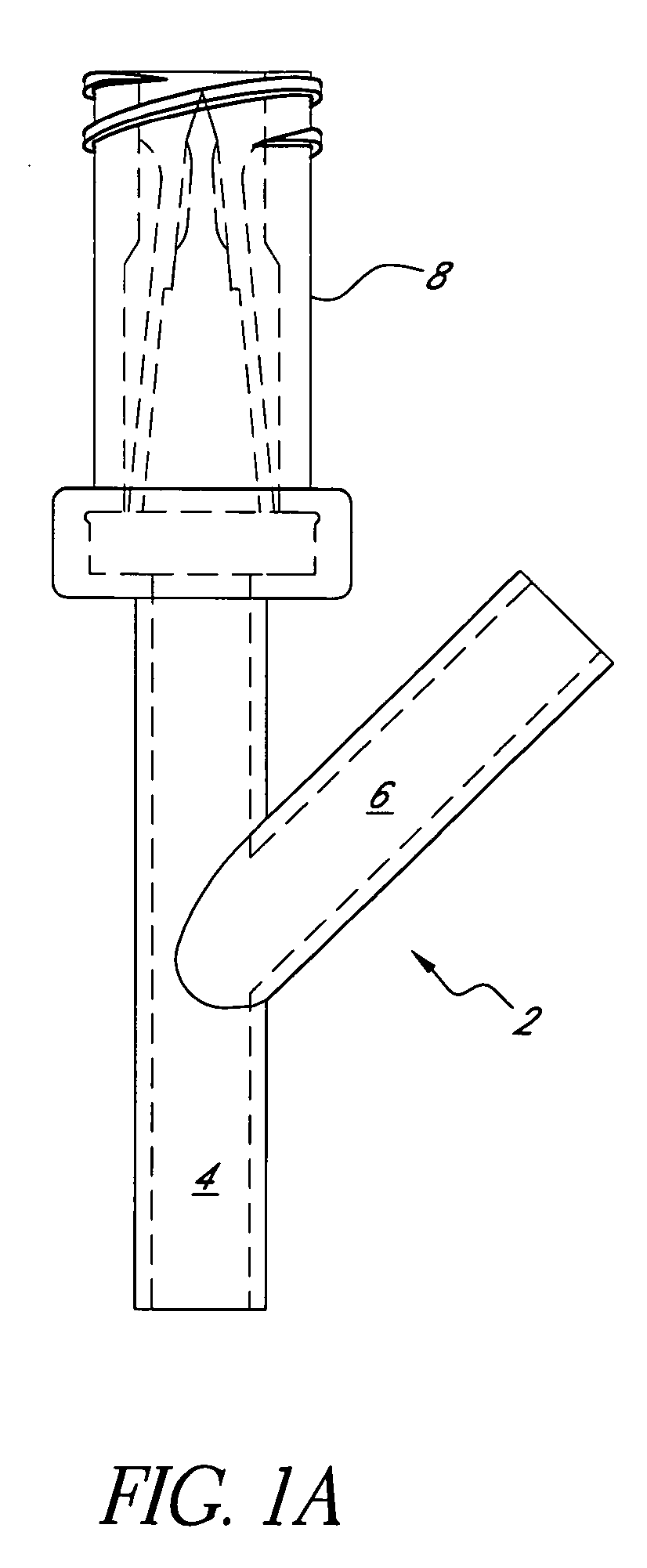
[0029] With reference to the attached figures, various embodiments of a Y-site check valve will now be described. FIG. 1A illustrates an example of a Y-site 2 with a needle-less connector 8 as illustrated and described in U.S. Pat. No. 6,599,273, incorporated herein by reference for all that it discloses. The illustrated needle-less connector8 is a version of the CLAVE® needle-less connector sold by ICU Medical, Inc, San Clemente, Calif.

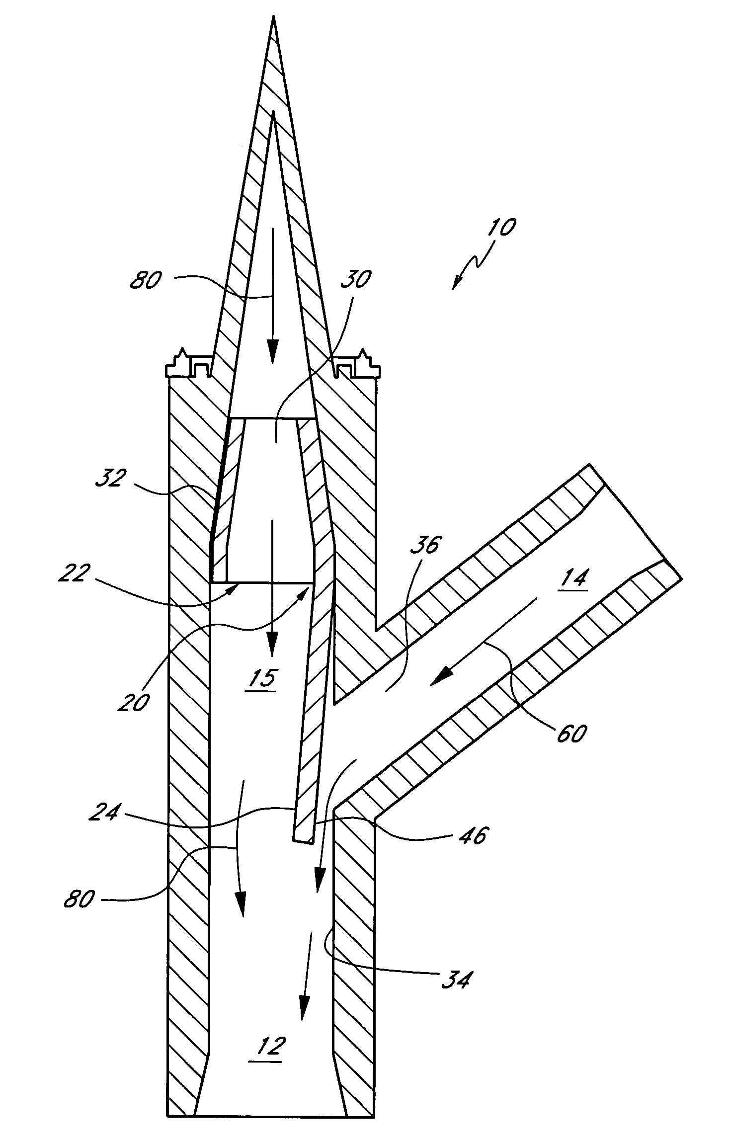
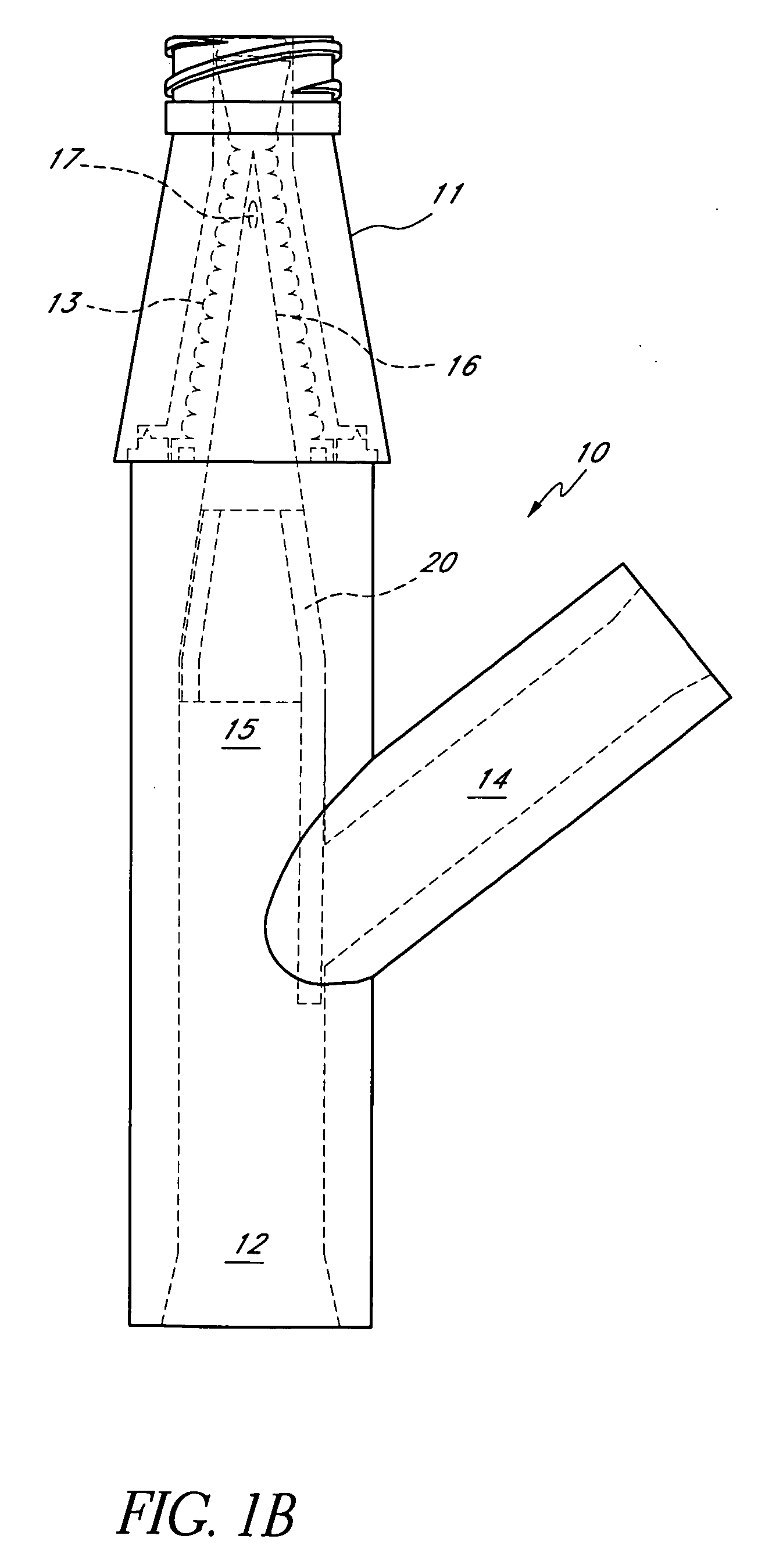
[0030]FIG. 1B illustrates an embodiment of a Y-site 10 with a check valve 20 configured to prevent backflow from the common lumen 12 or secondary lumen 15 into the main drip lumen 14. In the illustrated embodiment, the Y-site 10 is attached to another version of the CLAVE® needle-less connector at its proximal end. The illustrated needle-less connector includes an outer housing 11, an inner seal element 13, and at tapered inlet port 16. Another medical implement, such as a syringe with a luer, can be inserted into the proximal opening of the connect...


PUM


Abstract

A check valve for use in a Y-site in an infusion system comprises a fixation portion configured to retain the check valve in a common lumen of the Y-site, and a flap member extending axially from the fixation portion. The flap member has an outer surface, at least a portion of which is configured to engage an internal wall of the common lumen overlying an inlet from a main lumen. In one embodiment, the flap member comprises a pocket surrounding the hole and any burr extending from the wall adjacent the hole. In some embodiments, the flap member is resiliently biased towards a sealed position, and can flex to allow fluid flow from the main lumen to the common lumen.

Description

BACKGROUND [0001] 1. Field of the Invention [0002] This invention relates in general to the field of medical fluid connectors, and in particular to a check valve for use in a medical Y-site connector. [0003] 2. Description of the Related Art [0004] Intravenous delivery of fluids has become an important aspect of modern medicine. Infusion systems are used to deliver hydrating and nourishing fluids, antibiotics, anesthetics, and other medications to patients. Infusion systems typically include a bag of fluid joined to a fluid line which is connected to an IV needle or catheter inserted into a patient's blood vein, thereby allowing the fluid to be dripped from the bag and into the patient. [0005] In many infusion systems, Y-sites are placed in the fluid line, between the fluid bag and the needle or catheter, to provide a second path through which other fluids or drugs can be injected into the infusion system. Standard Y-sites are so named because a fork is created between a main lumen ...

Claims


Application Information

Patent Timeline
IPC IPC(8): A61M5/00
CPCA61M39/24A61M39/26A61M2039/2433A61M2039/244Y10T137/7891
Inventor FANGROW, THOMAS F. JR.
Owner ICU MEDICAL INC
Why Eureka
Try Eureka