Localizing a remote event timestamp from a network device with an independent clock method and apparatus

Inactive Publication Date: 2006-08-03
ASCOM SWEDEN
View PDF5 Cites 30 Cited by
  • Summary
  • Abstract
  • Description
  • Claims
  • Application Information

AI Technical Summary

Problems solved by technology

In some situations, these requirements may not be available to the system.
Furthermore, most

Method used


Image

  • Localizing a remote event timestamp from a network device with an independent clock method and apparatus
  • Localizing a remote event timestamp from a network device with an independent clock method and apparatus
  • Localizing a remote event timestamp from a network device with an independent clock method and apparatus

Examples


Embodiment Construction

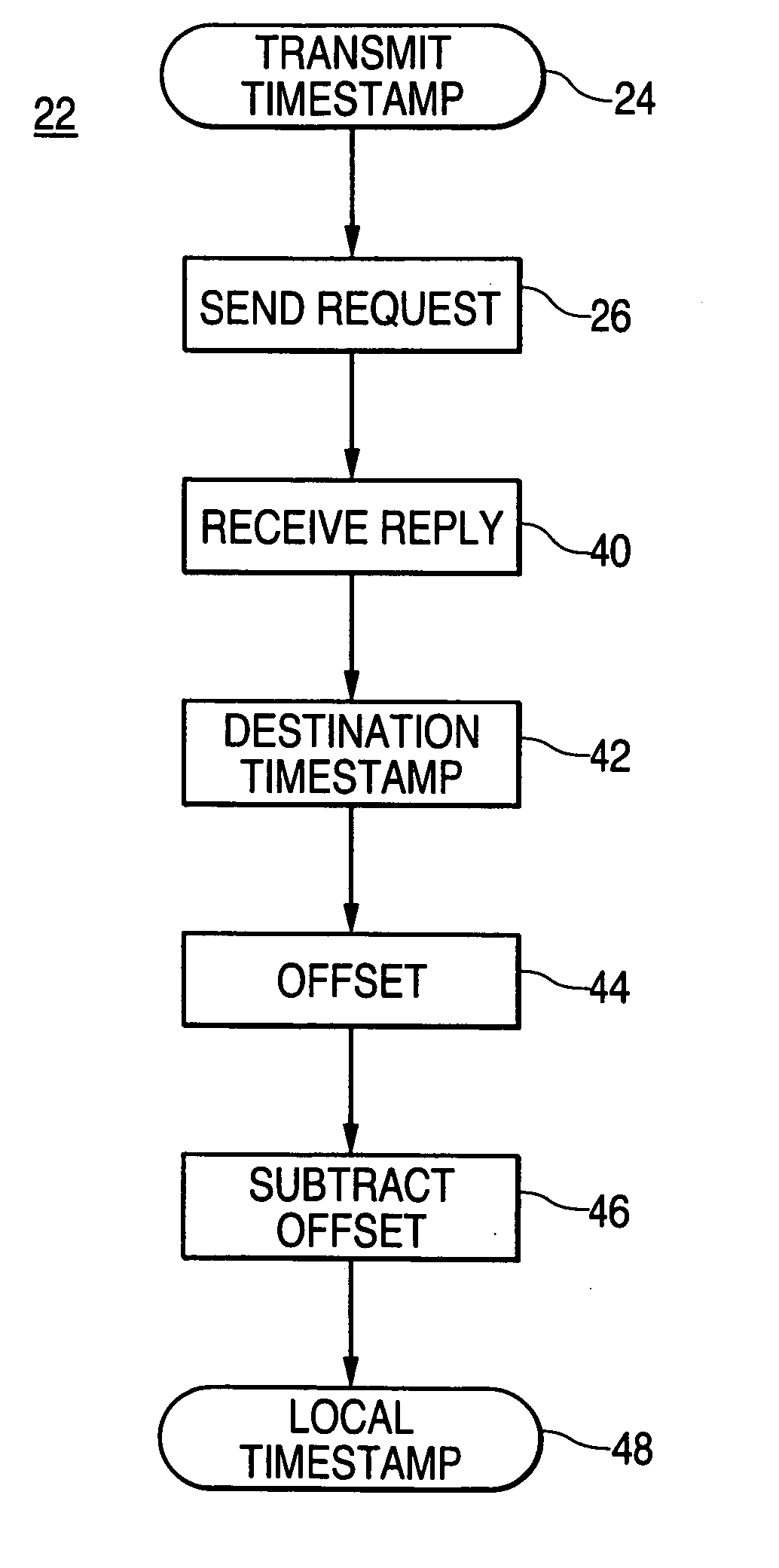
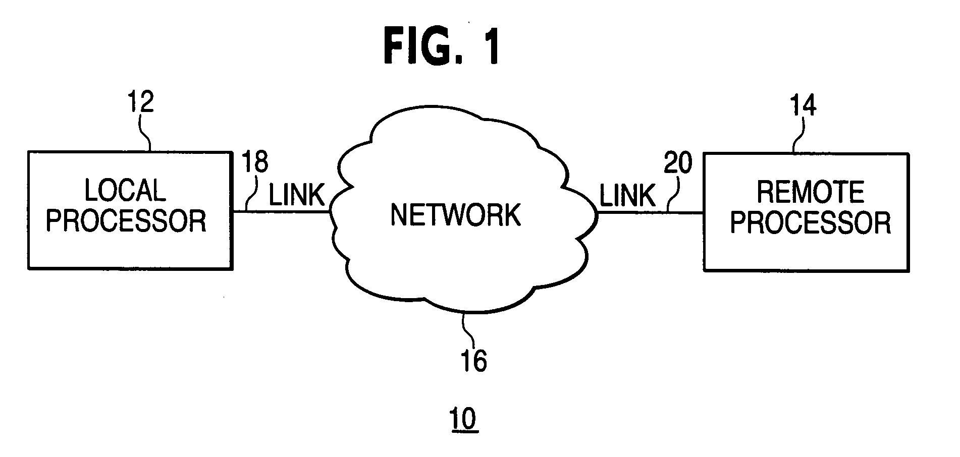
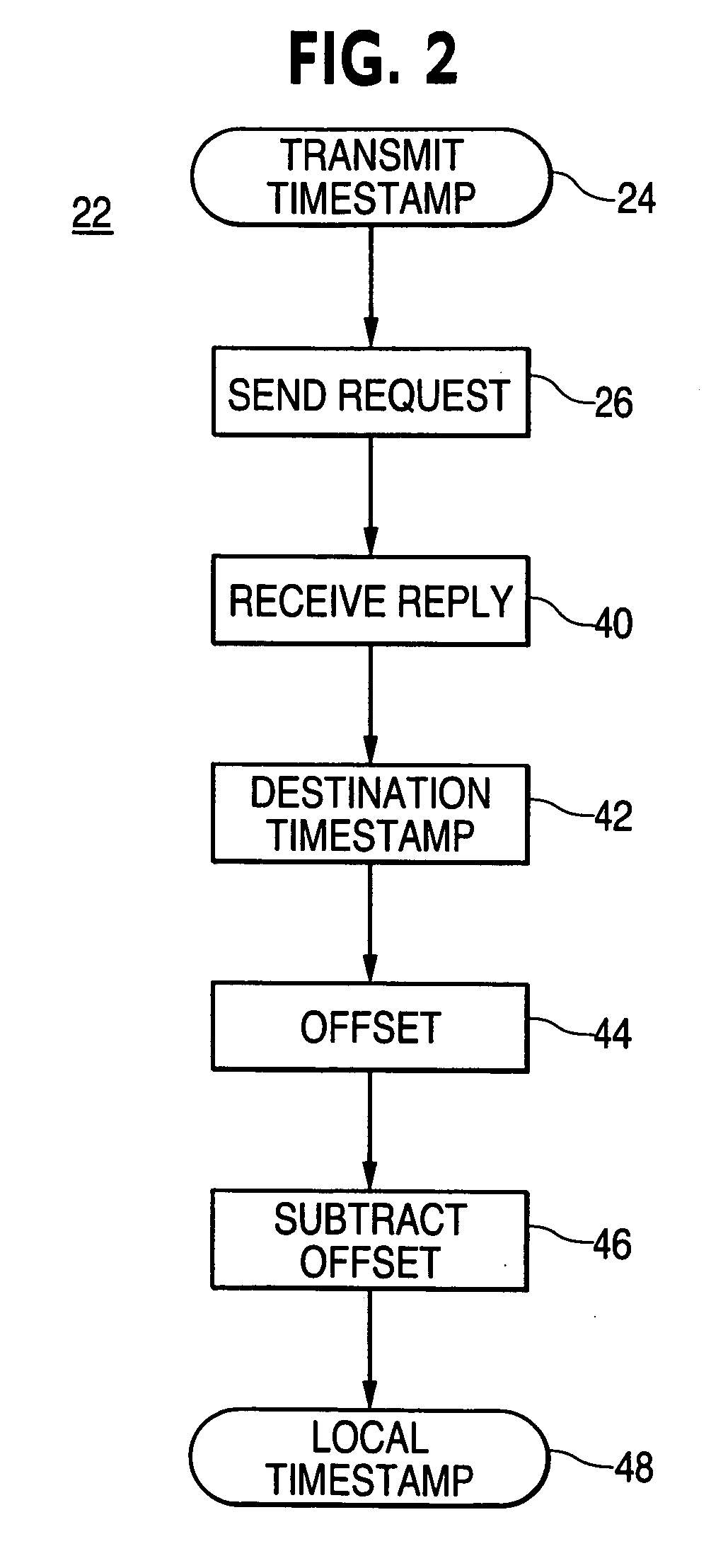
[0017] The invention will now be described with reference to the drawing figures, in which like reference numerals refer to like parts throughout. For the purposes of this discussion, the time according to the clock in the local processor 12 will be referred to as local time and the time according to the clock in the remote processor 14 will be referred to as remote time. An embodiment in accordance with the present invention provides a local computer or processor, a remote computer or processor, and a network linking the local computer and the remote computer. A request message is sent from the local computer to the remote computer containing a local transmit timestamp. A reply message is then sent from the remote computer to the local computer containing an originate timestamp, a receive timestamp, a remote transmit timestamp and a remote event timestamp. Upon receiving the reply message, the local computer sets a destination timestamp and calculates a local timestamp that corresp...


PUM


Abstract

A timestamp localization method and device includes two processors with independent clocks connected to a communication network. Two messages are exchanged between the processors. First a request message is sent with a transmit timestamp. Second, a reply message is sent back with receive, originate, transmit and remote timestamps. Then the remote timestamp is converted to a local timestamp using an algorithm and the timestamps from the reply message.

Description

FIELD OF THE INVENTION [0001] The present invention relates generally to computer networks. More particularly, the present invention relates to time stamping for network devices with independent clocks. BACKGROUND OF THE INVENTION [0002] The proliferation of computer networks has necessitated the development of methods for justifying the time settings on individual computers connected to a network. For example, when any event that has a temporal component occurs in one computer connected to a communications network, and the event needs to be conveyed from that computer to another computer on the network, the time recorded by the first computer must be justified to the time kept by the second computer. A solution has been to implement a real-time clock in each device synchronized to the time kept on a real-time server using, for example, the simplified network time protocol (SNTP), which is defined in Request for Comments (RFC) 2030. SNTP is an adaptation of the network time protocol...

Claims


Application Information

Patent Timeline
IPC IPC(8): G06F15/16
CPCH04J3/0667H04L69/28
Inventor COYLE, JONATHAN V.
Owner ASCOM SWEDEN
Why Eureka
Try Eureka