Eureka AIR delivers breakthrough ideas for toughest innovation challenges, trusted by R&D personnel around the world.

Automated remote monitoring system for construction sites

Inactive Publication Date: 2006-08-03
MATTERN BRYAN +2
View PDF3 Cites 60 Cited by
  • Summary
  • Abstract
  • Description
  • Claims
  • Application Information

AI Technical Summary

Benefits of technology

[0008] These and other features, aspects and embodiments

Problems solved by technology

However, the resolution of such videos is very low to facilitate the speed and bandwidth that most individuals have access to in using the Internet.
In particular, many construction sites do not have access to high bandwidth connections to the Internet.
The low resolution of these webcam images greatly limits their usage for applications where a larger, clearer picture is desired.
For example, a security camera webcam feed may indicate an intruder, but may be unable to provide a picture clear enough to identify the individual, thus limiting its usefulness for an online security application.
Construction project managers have long struggled with finding ways to effectively monitoring construction sites.
Many project managers are overseeing multiple projects in multiple locations and cannot have their eye on every aspect of each project all the time.
Equipment is commonly stolen from project sites, as unscrupulous individuals recognize the difficulty that a project manager would have in monitoring the site.
A further difficulty exists for project managers in tracking the progress of a particular project.
For example, construction on a project is often delayed due to weather.
However, there exists opportunities for workers to take days and time off when the weather truly does not necessitate it and the project manager cannot be on site every minute to monitor the weather condition.
While generic weather data is available for general areas, this information is commonly not accurate enough to indicate the actual weather occurring at a particular location.
The use of traditional web cameras to monitor construction project sites for purposes of security and project monitoring has a number of problems that makes it impractical and relatively inept for those purposes.
For example, many construction sites do not have dedicated high-bandwidth connections to the Internet available to facilitate streaming video at a resolution that would allow a project manager to monitor individuals effectively at the project site.
Furthermore, the use of traditional web cameras does not allow the archiving of images for the life of the project so that a project manager would be able to confirm events based on a particular date and time in the past.

Method used


Image

  • Automated remote monitoring system for construction sites
  • Automated remote monitoring system for construction sites
  • Automated remote monitoring system for construction sites

Examples


Embodiment Construction

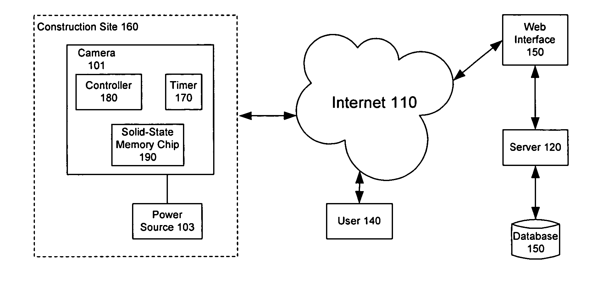
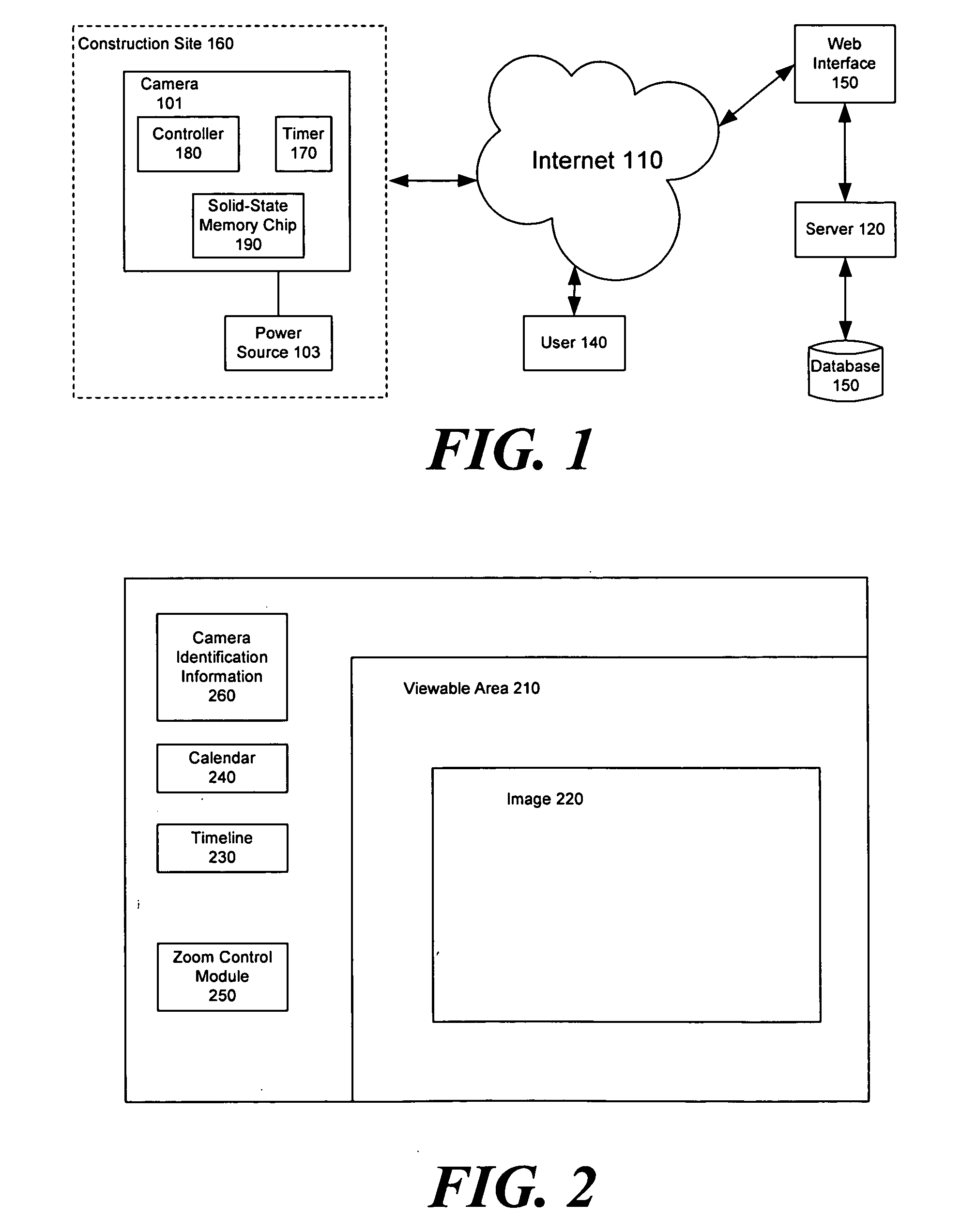
[0014] The system of the preferred embodiment may be described by reference to the figures. FIG. 1 is a block diagram illustrating an exemplary system in accordance with certain embodiments of the present invention. The digital camera 101 should be capable of taking high-resolution images, where high-resolution refers to images stored at a resolution greater than 640×480 pixels. In alternative embodiments of the invention, the camera 101 is powered through a solar panel system which generates the power necessary to operate the digital camera 101. In the preferred embodiment, the camera 101 operates through a wired power source 103.

[0015] The camera 101 is located at a construction site 160 which is located remotely from the central server 120. Each construction site 160, in the preferred embodiment, may have multiple cameras 101 which communicate to the central server 120 through a connection to the Internet 110. The number of cameras 101 located at each remote construction site 16...


PUM


Abstract

The present invention relates generally to automated remote monitoring of construction projects. More particularly, the present invention relates to systems and methods for providing worldwide access to high-resolution images of construction projects, where the images are archived through the life of the project and can be accessed through secure connections to the Internet.

Description

TECHNICAL FIELD [0001] The present invention relates generally to automated remote monitoring of construction projects. More particularly, the present invention relates to systems and methods for providing global access to high-resolution images of construction projects, where the images are archived through the life of the project and can be accessed through secure connections to the Internet. BACKGROUND OF THE INVENTION [0002] Webcams have long been used to provide streaming video which may be accessed through the Internet. Individuals may access the Internet through the use of web browsers or other software and can view these streaming videos on the displays of their computers. However, the resolution of such videos is very low to facilitate the speed and bandwidth that most individuals have access to in using the Internet. In particular, many construction sites do not have access to high bandwidth connections to the Internet. The low resolution of these webcam images greatly lim...

Claims


Application Information

Patent Timeline
IPC IPC(8): H04N7/173H04N7/18H04N9/47
CPCH04N7/18
Inventor MATTERN, BRYANPAULSON, JOHNMCCORMACK, CHANDLER
Owner MATTERN BRYAN
Why Eureka
Eureka Blog
Learn More