Water resistant switch mat having activation across its entire surface

a technology of activation and switch, applied in the direction of contact mechanism, contact surface shape/structure, contact surface, etc., can solve the problem that the mat does not produce the desired effect, and achieve the effect of minimizing tripping

Active Publication Date: 2006-08-10
TAPESWITCH OF AMERICA
View PDF7 Cites 4 Cited by
  • Summary
  • Abstract
  • Description
  • Claims
  • Application Information

AI Technical Summary

Benefits of technology

[0011] In a preferred embodiment, the electrical switch mat further includes at least one interior ribbon switch disposed between the first layer and the second layer and spaced inwardly from the perimeter ribbon switch. In this manner, the electrical switch mat is pressure-sensitive across the entire surface of the first and second layers. Also, the peripheral edges of the first and second layers are bonded together with the longitudinal edge of the ribbon switch to form a continuous perimeter of the switch mat. The flexible matting material of the first and second layers is preferably an elastic water-resistant material and the first layer of flexible matting material may include an inclined ramp portion adjacent the peripheral edge for minimizing tripping on the switch mat.

Problems solved by technology

This results in the mats not producing the desired effect, i.e., the detection of movement of objects or people thereacross.

Method used


Image

  • Water resistant switch mat having activation across its entire surface
  • Water resistant switch mat having activation across its entire surface
  • Water resistant switch mat having activation across its entire surface

Examples


Embodiment Construction

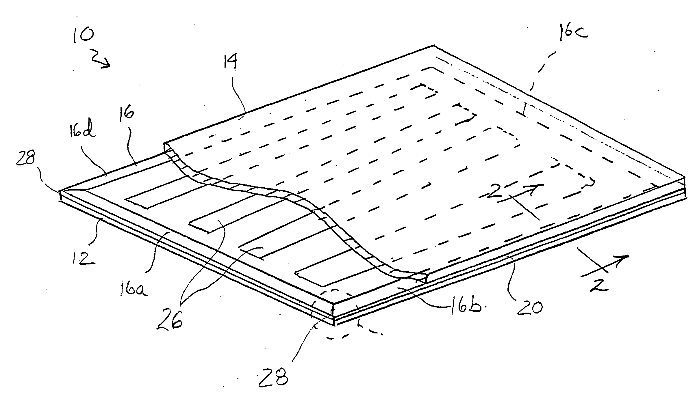
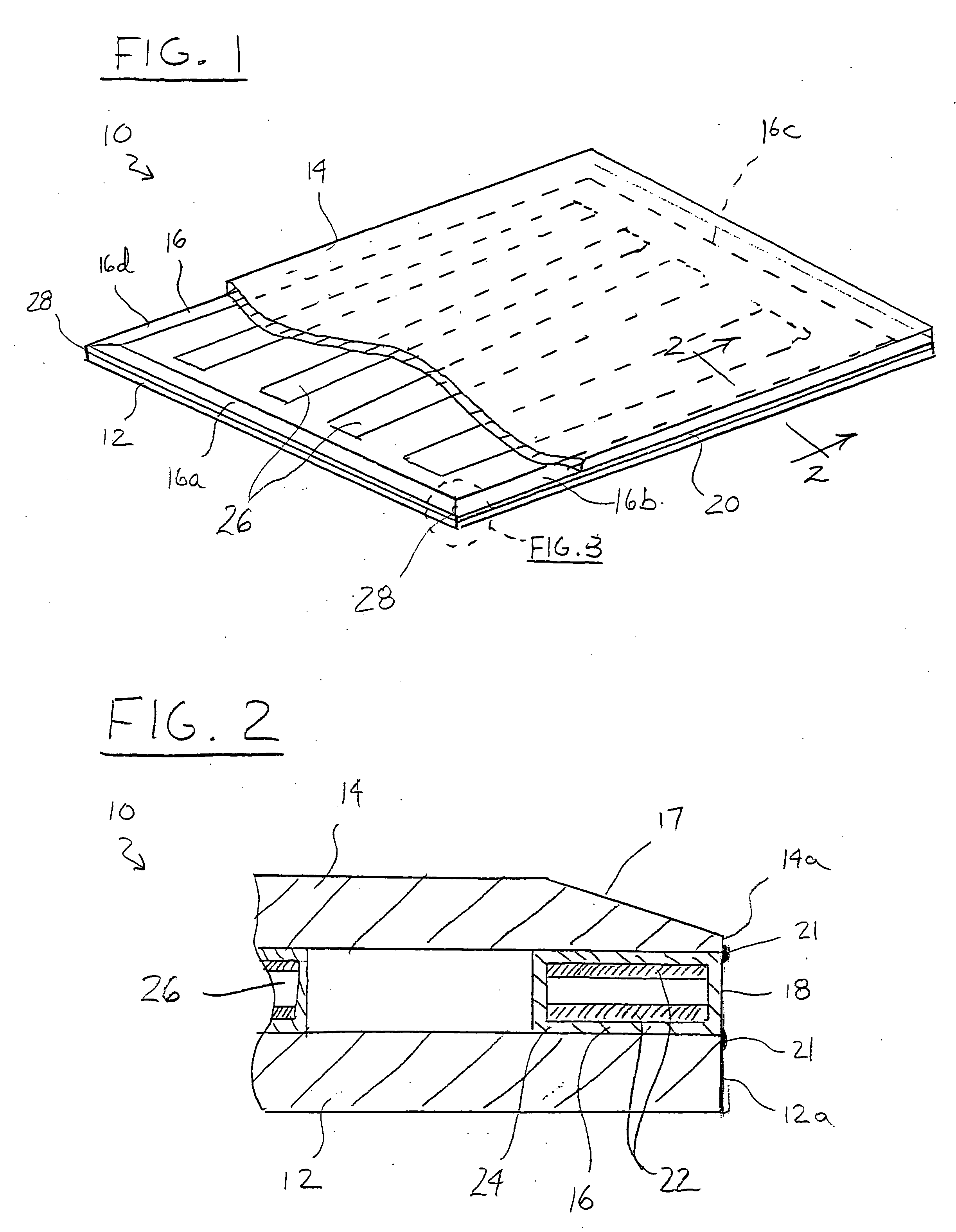
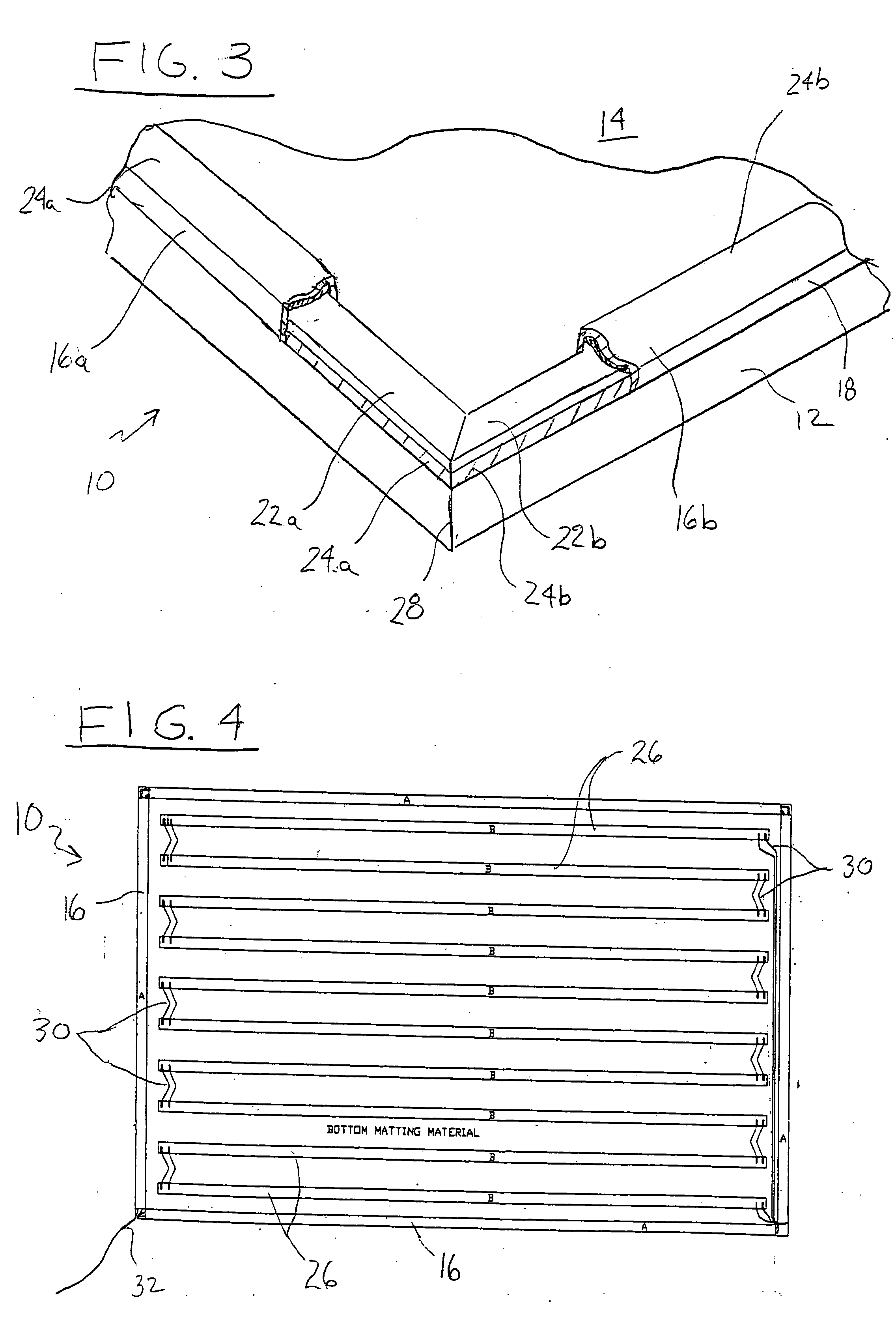
[0020] Referring first to FIGS. 1 and 2, an electrical switch mat 10 formed in accordance with the present invention is shown. The electrical switch mat 10 generally includes a first layer 12 of flexible matting material, a second layer 14 of flexible matting material and a perimeter ribbon switch 16 disposed in a laminated manner between the first and second layers. The flexible matting material is preferably a durable elastic and water-resistant material, such as a polyvinyl chloride (PVC) material.

[0021] The first and second layers 12 and 14 are of the same size and shape so that their respective peripheral edges 12a and 14a will be aligned when the layers are laminated together. As shown in FIGS. 1-3, the first layer 12 forms the bottom of the switch mat 10, which would generally rest against a floor surface, and the second layer 14 forms the top of the switch mat, which would generally be subject to pedestrian or other traffic. Preferably, the top layer 14 includes an inclined...


PUM

PropertyMeasurementUnit
angleaaaaaaaaaa
flexibleaaaaaaaaaa
pressureaaaaaaaaaa

Abstract

An electrical switch mat which generally includes a first layer of flexible matting material, a second layer of flexible matting material, and a perimeter ribbon switch disposed between the first layer and the second layer. The ribbon switch has a longitudinal edge and is operable under pressure between a closed condition and an open condition and maintained in one of the open and closed conditions in the absence of pressure. The first and second layers have a peripheral edge which is aligned with the longitudinal edge of the ribbon switch in a coplanar relationship to form a peripheral edge of the electrical switch mat.

Description

BACKGROUND OF THE INVENTION [0001] The present invention relates generally to pressure activated switches, and more particularly, to a sensing mat having pressure activated switches contained therein for optimum surface area activation. [0002] Various types of electrical switch mats are known in the art. Electrical switch mats have been designed for use in many different applications including use in floor mats for security, safety or other purposes to detect movement of objects or pedestrian traffic thereover. For example, it is known in the art to provide sensing mats or switch mats as part of a safety system to protect persons from injury from dangerous machinery and industrial equipment. Examples of such safety systems utilize switch mats connected to a machine controller for terminating power to the machine if someone steps on or off the mat. [0003] Generally, electrical switch mats include one or more pressure-actuated switches incorporated within a floor mat material which pr...

Claims


Application Information

Patent Timeline
Patent Type & Authority Applications(United States)
IPC IPC(8): H01H35/00
CPCH01H3/141H01H2003/147H01H2003/148
Inventor GRZAN, JOHN
Owner TAPESWITCH OF AMERICA
Why Eureka
Try Eureka