Method and apparatus for increasing load bearing capacity of a tubular string

a technology of load-bearing capacity and tubular pipe, which is applied in the direction of drilling casings, wellheads, well accessories, etc., can solve the problems of insufficient load-bearing capacity of conductor strings, more complex and heavier operational equipment, and procedures that do not allow time for tubular pipes or strings to remain undisturbed, etc., to achieve the effect of increasing the load-bearing capacity of tubular pipes or strings, increasing the load-bearing capacity of tubular pipes

Active Publication Date: 2015-11-10
YUSUF OSMAN
View PDF16 Cites 3 Cited by
  • Summary
  • Abstract
  • Description
  • Claims
  • Application Information

AI Technical Summary

Benefits of technology

[0013]In another aspect of the present invention, a method of deploying a load-bearing capacity increaser assembly can be installed on a tubular string in the un-set configuration, and deployable within the borehole to provide an increase in the load-bearing capacity of a tubular pipe or string, wherein the method can include reshaping the apparatus within the targeted interval of the borehole to create an upset or right angle greater than the outside diameter of the tubular pipe or string and greater than the inside diameter of the borehole, in effect setting the apparatus within said targeted interval of the borehole.
[0014]In another aspect of the present invention, a method of deploying a load-bearing capacity increaser assembly can be installed on a tubular string in the un-set configuration, and deployable within the borehole to provide an increase in the load-bearing capacity of a tubular pipe or string, wherein the method can include pushing the internal spears outwardly through the apparatus into the earth past the inside diameter of the borehole, in effect setting the apparatus within the targeted interval of the borehole.
[0015]In another aspect of the present invention, a method of deploying a load-bearing capacity increaser assembly can be installed on a tubular string in the un-set configuration, and deployable within the borehole to provide an increase in the load-bearing capacity of a tubular pipe or string, wherein the method can include opening the external spears or skirt outwardly from the tubular pipe or string into the earth past the inside diameter of the borehole, in effect setting the apparatus within the targeted interval of the borehole.
[0016]In another aspect of the present invention, an apparatus is provided for increasing the load bearing capacity of a tubular string having a first body coupled to the string, two or more members coupled to the first body, wherein the two or more members are configured to move with respect to the first body, the two or more members each further include a distal end having one or more of an acute, pointed, tapered, or sharp configuration, and a second body configured to cause the two or more members of the first body to move radially outwardly, wherein the distal ends of the two or more members penetrate the earth. In addition, the two or more members can be comprised of one or more of blades, fins, wings, spearheads, and rods. Further, the two or more members can expand the diameter of the first body. The two or more members may also pivot with respect to the first body. The two or more may also include an inverted cone or gussets configured to expand radially outward.
[0017]In another aspect of the present invention, a method of increasing the load bearing capacity of a tubular string can include positioning a first body coupled to the string within a borehole, wherein the first body includes a plurality of members for penetrating the earth, the members having a distal end with a tapered configuration, and positioning a second body through the string and adjacent to the second body, wherein the second body at least partially engages the first body, thereby causing the members to move with respect to the first body and penetrate the earth, thereby increasing the load bearing capacity of the string. Further, the earth penetrated engaged members of the first body provide space between the first body and the earth thereby allowing fluid to pass through the borehole around the string. The method can further include jetting or piling the string into the earth prior to the parts of the first body having penetrated the earth. The method can also include cementing the string in the borehole after the parts of the first body have penetrated the earth.

Problems solved by technology

When placing the conductor string into the earth using the aforementioned traditionally prevailing methods, conductor strings generally appear to provide adequate load-bearing capacity for the aforementioned operational equipment, although from time to time it is also common even in these traditional methods for conductor strings to sink after they are initially set, in some cases occurring immediately to during the drilling and well construction process up to decades later during production or even abandonment, always due to inadequate load-bearing capacity.
As drilling depths increase, more complex and heavier operational equipment, especially wellheads, blowout preventers, and casing strings are being employed.
Also, in some instances, unforeseen and / or unique circumstances involving formation, formation plasticity, formation set-up, cement job, cement composition, cement bond, conductor pipe, conductor pipe bond, connectors, assemblies, and other down-hole variables may cause inadequate load-bearing capacity in a conductor string.
This varies depending on multiple factors, mainly formation plasticity, but typical well construction procedures do not allow time for a tubular pipe or string remaining in undisturbed contact with the earth after placement mainly due to the economics of the practice.
These costs can include but are not limited to drilling rig day rates, other daily spread costs and opportunity costs associated with late delivery of well production.
Consequently, there exists a lack of expertise in the practice.

Method used


Image

  • Method and apparatus for increasing load bearing capacity of a tubular string
  • Method and apparatus for increasing load bearing capacity of a tubular string
  • Method and apparatus for increasing load bearing capacity of a tubular string

Examples


Embodiment Construction

[0031]While preferred embodiments of the LBCI have been shown and described herein, it will be obvious to those skilled in the art that such embodiments are provided by way of example only. Numerous variations, changes, and substitutions will now occur to those skilled in the art without departing from the invention. It should be understood that various alternatives to the embodiments of the invention described herein may be employed in practicing the invention.

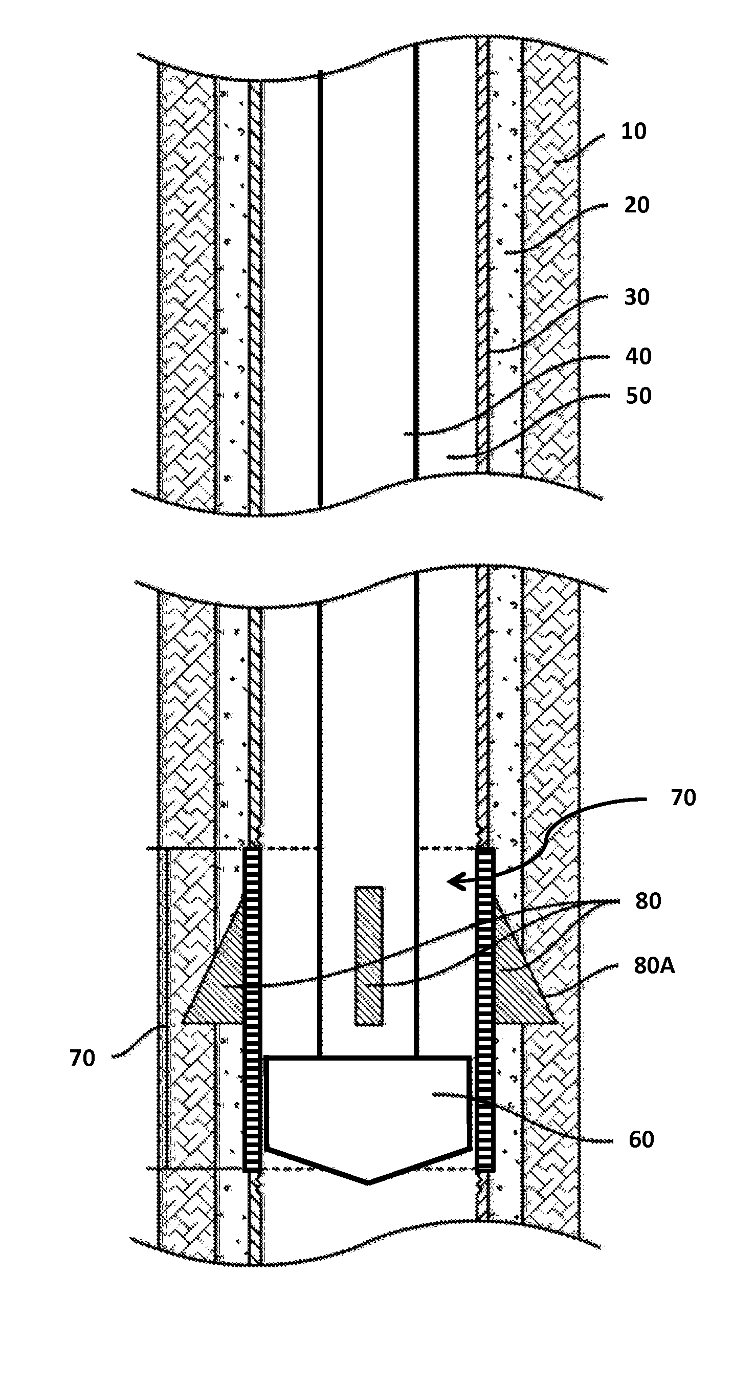
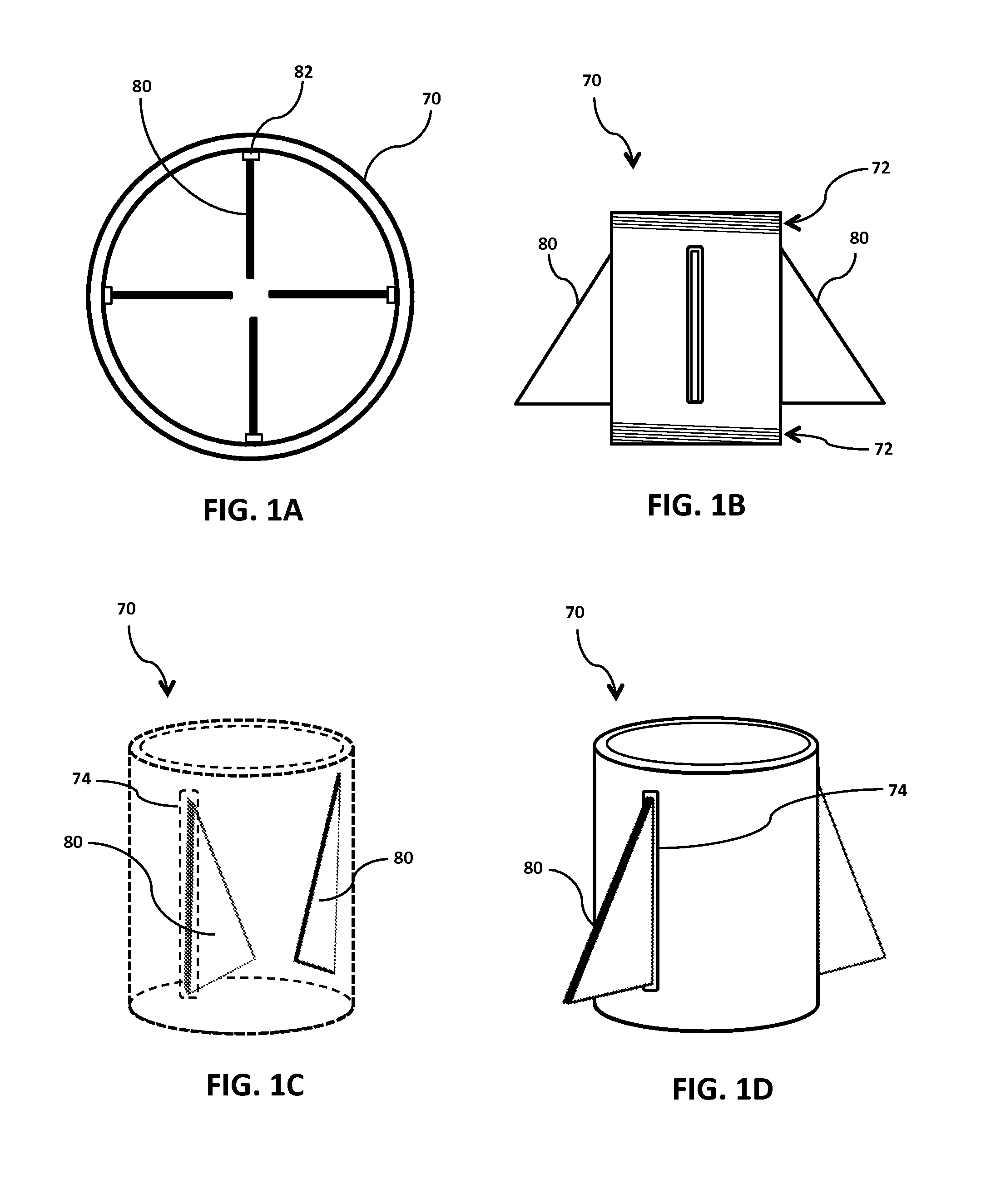
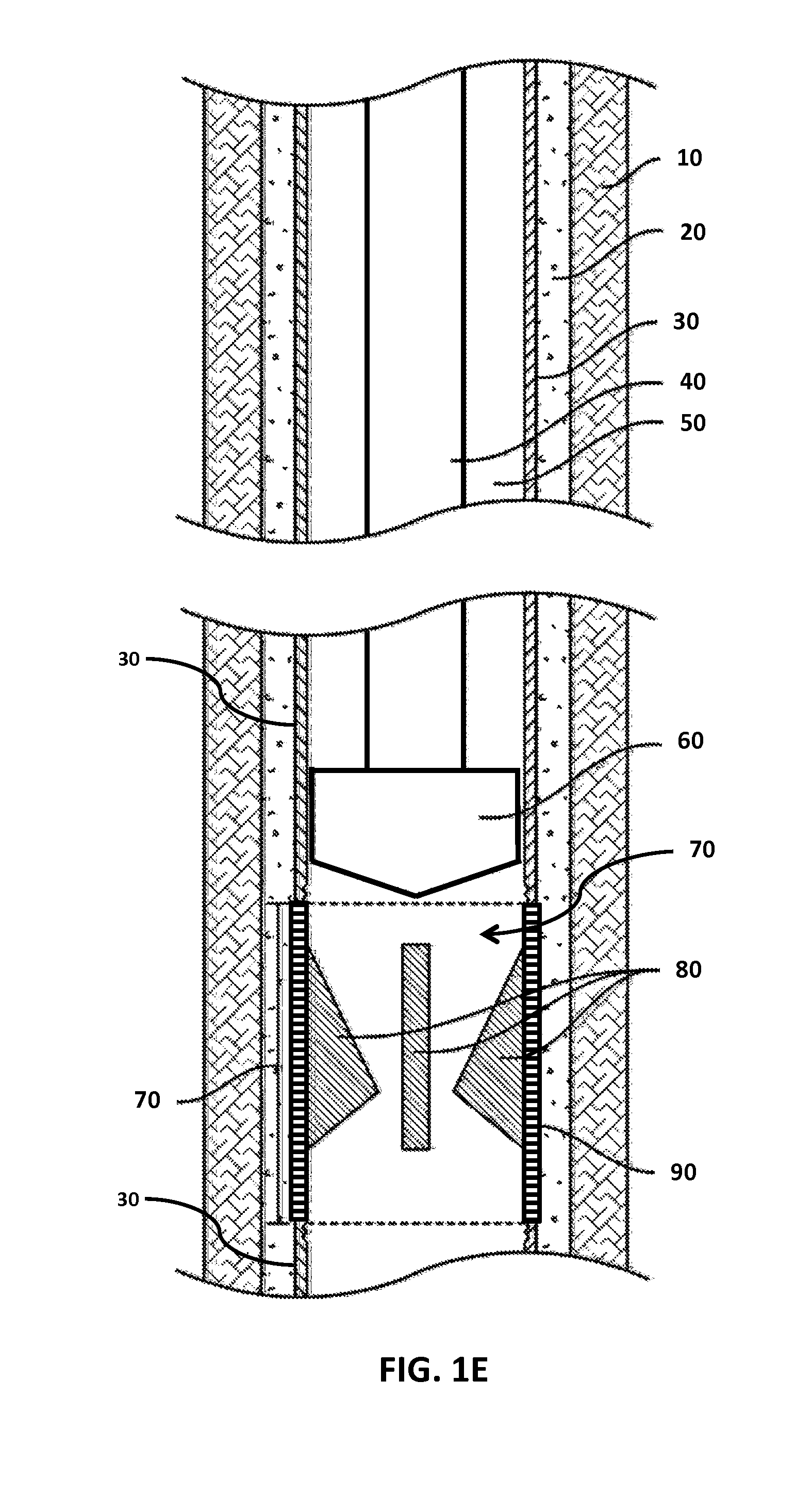
[0032]FIG. 1A-1D illustrate various views for one embodiment of the LBCI apparatus of the present invention. Here, LBCI apparatus 70 can include a plurality of parts or members 80, which can also be referred to herein as blades, fins, wings, spears, protrusions, projectiles, gussets, among others. Here, parts 80 can be disposed within the interior volumetric space of the LBCI apparatus 70, as shown in FIG. 1A and FIG. 1C. Further, members 80 can pivot about a hinge 82 thereby projecting or protruding outwards, as shown in FIG...


PUM


Abstract

An apparatus for increasing a load bearing capacity of a tubular string having a first body coupled to the string, two or more members coupled to the first body, and wherein the two or more members are configured to move with respect to the first body. The two or more members each further include a distal end having one or more of an acute, pointed, tapered, or sharp configuration. In addition, a second body is configured to cause the two or more members of the first body to move radially outwardly, wherein the distal ends of the two or more parts penetrate the earth and thereby increase the load bearing capacity of the tubular string.

Description

CROSS REFERENCE TO RELATED APPLICATIONS[0001]This application claims the benefit of U.S. Provisional Application No. 62 / 028,878 filed on Jul. 25, 2014, which is incorporated herein by reference in its entirety.FIELD OF INVENTION[0002]The present document is generally related to an apparatus for and method of increasing the load-bearing capacity of a tubular string (referred to herein as “Load-Bearing Capacity Increaser” or “LBCI”), and more particularly an apparatus, system and / or method of increasing load-bearing capacity of a tubular pipe or string used in the construction of a well.BACKGROUND[0003]This section is intended to introduce the reader to aspects of art that may be related to various aspects of the present invention or present solution, which are described and / or claimed below. This discussion is believed to be helpful in providing the reader with background information to facilitate a better understanding of the various aspects of the present invention. Accordingly, it...

Claims


Application Information

Patent Timeline
Patent Type & Authority Patents(United States)
IPC IPC(8): E21B17/00E21B17/10E21B33/14E21B23/01
CPCE21B17/1021E21B33/14E21B23/01
Inventor YUSUF, OSMAN
Owner YUSUF OSMAN
Why Eureka
Try Eureka