Modular power source for electric ARC welding and output chopper

Active Publication Date: 2006-08-10
LINCOLN GLOBAL INC
View PDF99 Cites 87 Cited by
  • Summary
  • Abstract
  • Description
  • Claims
  • Application Information

AI Technical Summary

Problems solved by technology

Lower duty cycles resulted in higher primary currents and more losses.
Using a power source where the final stage is a regulated single stage inverter resulted in heat losses, lower efficiency, high cost and increased compo

Method used


Image

  • Modular power source for electric ARC welding and output chopper
  • Modular power source for electric ARC welding and output chopper
  • Modular power source for electric ARC welding and output chopper

Examples


Embodiment Construction

FIGS. 22-29

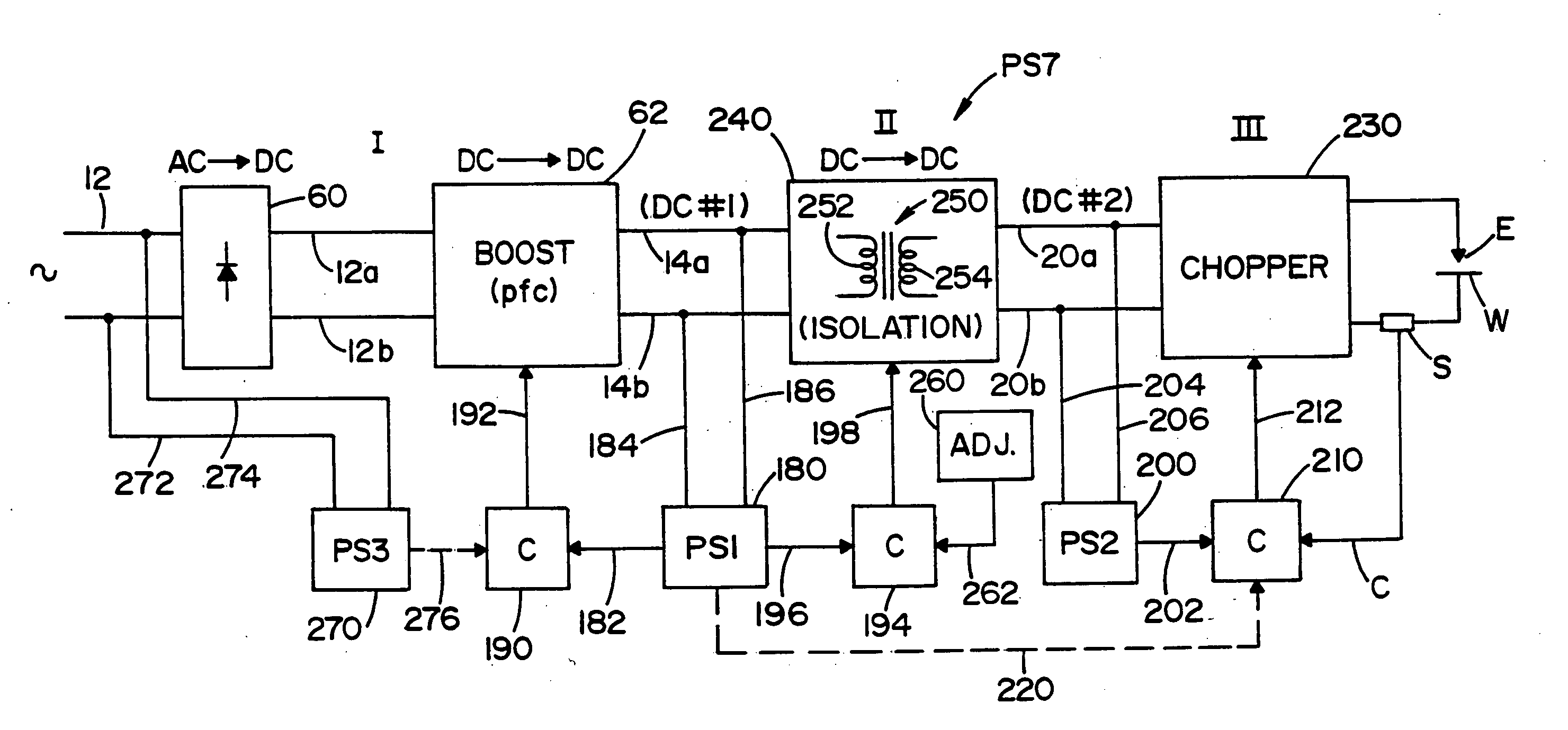
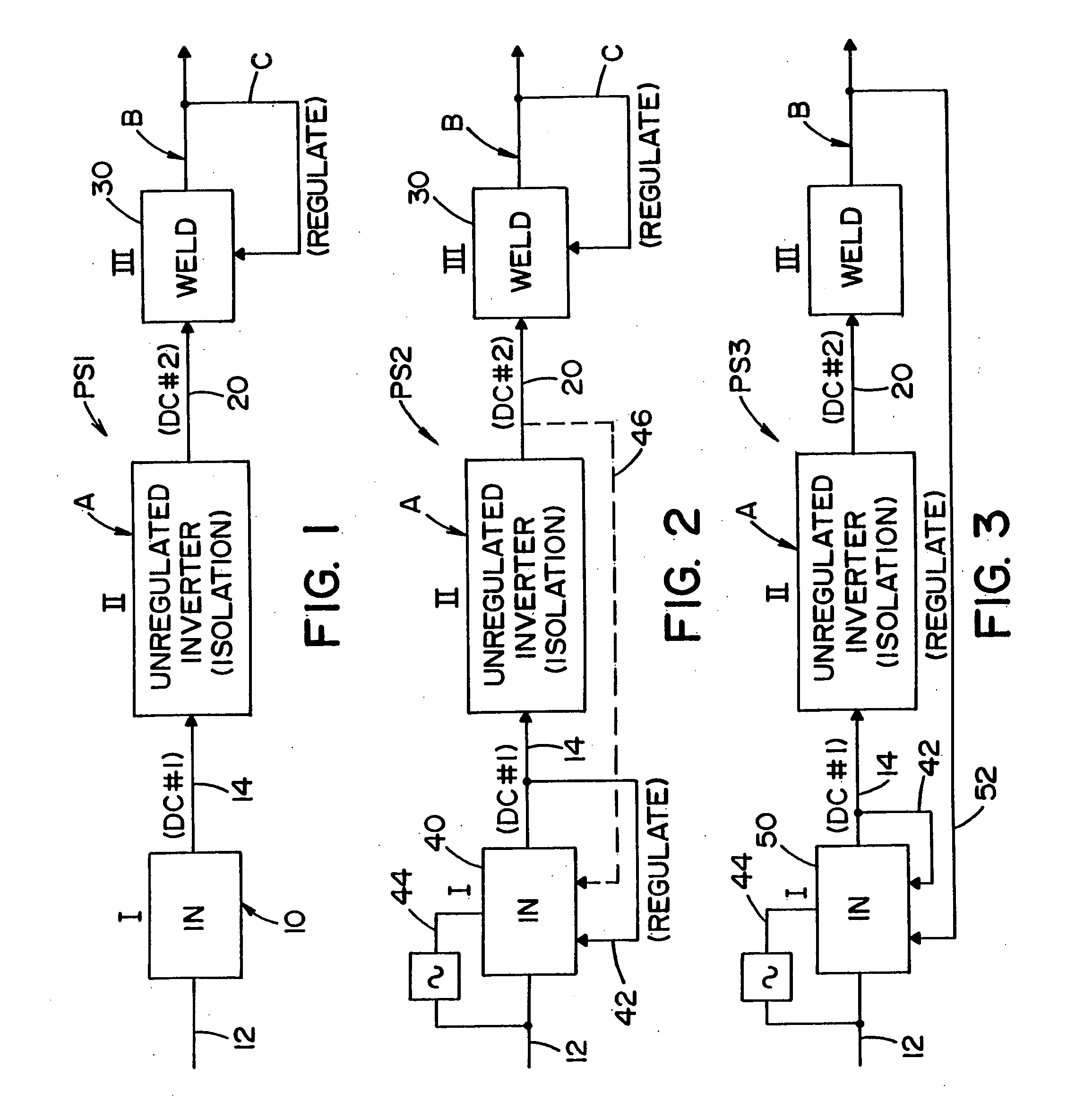
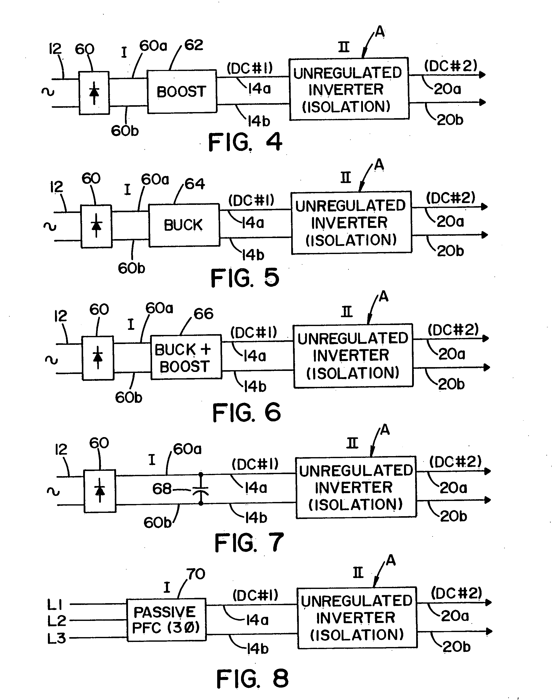
[0067] The three stage power source shown and described in FIGS. 1-21 constitute a substantial advance in the art of electric arc welding. The present invention involves this novel three stage power source, as generally represented in FIG. 11, formed into a modularized construction, as illustrated in FIG. 22. Power source 700 includes a first module 702 forming a fixed assembled frame on a single base. This module includes the first input stage 62 and the isolation or second stage, in the form of unregulated inverter A. As in FIG. 11, two controllers, shown in two stages such as controller 190 and controller 194, direct control signals on lines 192, 198 into the two separate stages of module 702. The output of first module 702 are lines 20a, 20b (DC #2). This output voltage is directed to a separate, second module or frame 704. The second frame supports the output third stage of the controller, illustrated as chopper 30 in FIGS. 11 and 22. Weld controller 210 controls the...


PUM

PropertyMeasurementUnit
Frequencyaaaaaaaaaa
Poweraaaaaaaaaa
Polarityaaaaaaaaaa

Abstract

A three stage power source for an electric arc welding process comprising an input stage having an AC input and a first DC output signal; a second stage in the form of an unregulated DC to DC converter having an input connected to the first DC output signal, a network of switches switched at a high frequency with a given duty cycle to convert the input into a first internal AC signal, an isolation transformer with a primary winding driven by the first internal high frequency AC signal and a secondary winding for creating a second internal high frequency AC signal and a rectifier to convert the second internal AC signal into a second DC output signal of the second stage; with a magnitude related to the duty cycle of the switches and, a third stage to convert the second DC output signal to a welding output for welding wherein the input stage and the second stage are assembled into a first module and the third stage is assembled into a second module connectable to the first module.

Description

[0001] The invention relates to the field of electric arc welding and more particularly to a modular power source for such welding and a novel dual mode chopper output stage for a welder. INCORPORATION BY REFERENCE AND BACKGROUND OF INVENTION [0002] Electric arc welding involves the passing of an AC or DC current between a metal electrode and a workpiece where the metal electrode is normally a cored metal wire or solid metal wire. A power source is used to create a given current pattern and / or polarity between the advancing electrode wire and workpiece so that the arc will melt the end of the advancing welding wire and deposit the molten metal on the workpiece. Although various converter technologies are used for power sources, the most effective is an inverter based power source where a switching network includes switches operated at high frequency to create the desired waveform or current level for the welding process. An inverter type power source is discussed in Blankenship U.S....

Claims


Application Information

Patent Timeline
IPC IPC(8): B23K9/10
CPCB23K9/09B23K9/1043B23K9/1075B23K9/173H02M1/4225Y02P70/10H02M1/007H02M1/0085H02M7/10H02M7/48
Inventor KOOKEN, TODD E.LUO, LIFENG
Owner LINCOLN GLOBAL INC
Why Eureka
Try Eureka