Hub for rolled wrap

a technology of rolled wrap and hub, which is applied in the field of rolled wrap hub, can solve the problems of unfavorable packaging, unfavorable packaging, and uneasy for users to tense stretch, and achieve the effects of convenient operation, smooth and firmly wrapping the article, and certain degree of elasticity

Inactive Publication Date: 2006-08-10
HUA WEI HSIU
View PDF7 Cites 18 Cited by
  • Summary
  • Abstract
  • Description
  • Claims
  • Application Information

AI Technical Summary

Benefits of technology

[0003] A primary object of the present invention is to provide a hub for rolled wrap, so that the rolled wrap may be more conveniently operated to perfectly package an article.
[0004] To achieve the above and other objects, the hub for rolled wrap according to the present invention includes a ring-shaped base having a sleeve portion axially extended from a rear end thereof, and a collar rotatably mounted on the sleeve portion of the base. An L-shaped curved holding-down plate is provided at a lower inner side of the base, and slits are formed at joints of the holding-down plate and the base and the sleeve portion to provide the holding-down plate with a certain degree of elasticity.
[0005] The hub is fitted in an open end of a rolled wrap with the collar rotatably mounted on the sleeve portion tightly contacting with a radially inner side of the rolled wrap. When the holding-down plate is not depressed, the rolled wrap can be freely rotated about the sleeve portion and outward pulled for wrapping an article, and when the holding-down plate is depressed to tightly press the sleeve portion against the collar, the rolled wrap is also held in place and a user may tensely stretch the outward pulled wrap to smoothly and firmly wrap the article.

Problems solved by technology

Since the conventional tubular member for rotatably holding the rolled wrap thereon does not include any means for holding the rolled wrap in place, it is uneasy for a user to tensely stretch the outward pulled portion of the rolled wrap to tightly wrap the article.
The outward pulled wrap tends to become loose, wrinkled, and biased, and fails to give the packaged article a nice appearance.

Method used


Image

  • Hub for rolled wrap
  • Hub for rolled wrap
  • Hub for rolled wrap

Examples


Embodiment Construction

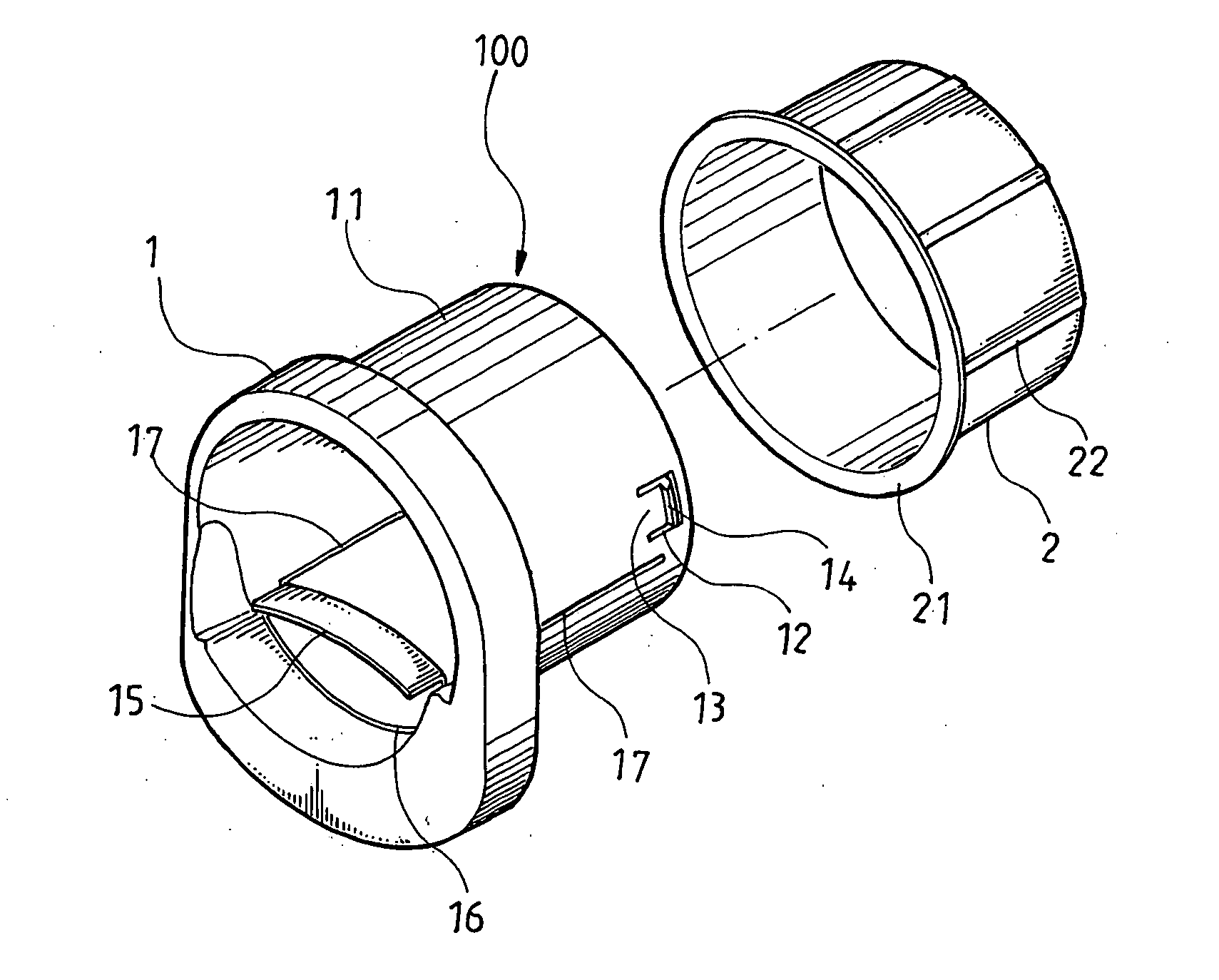
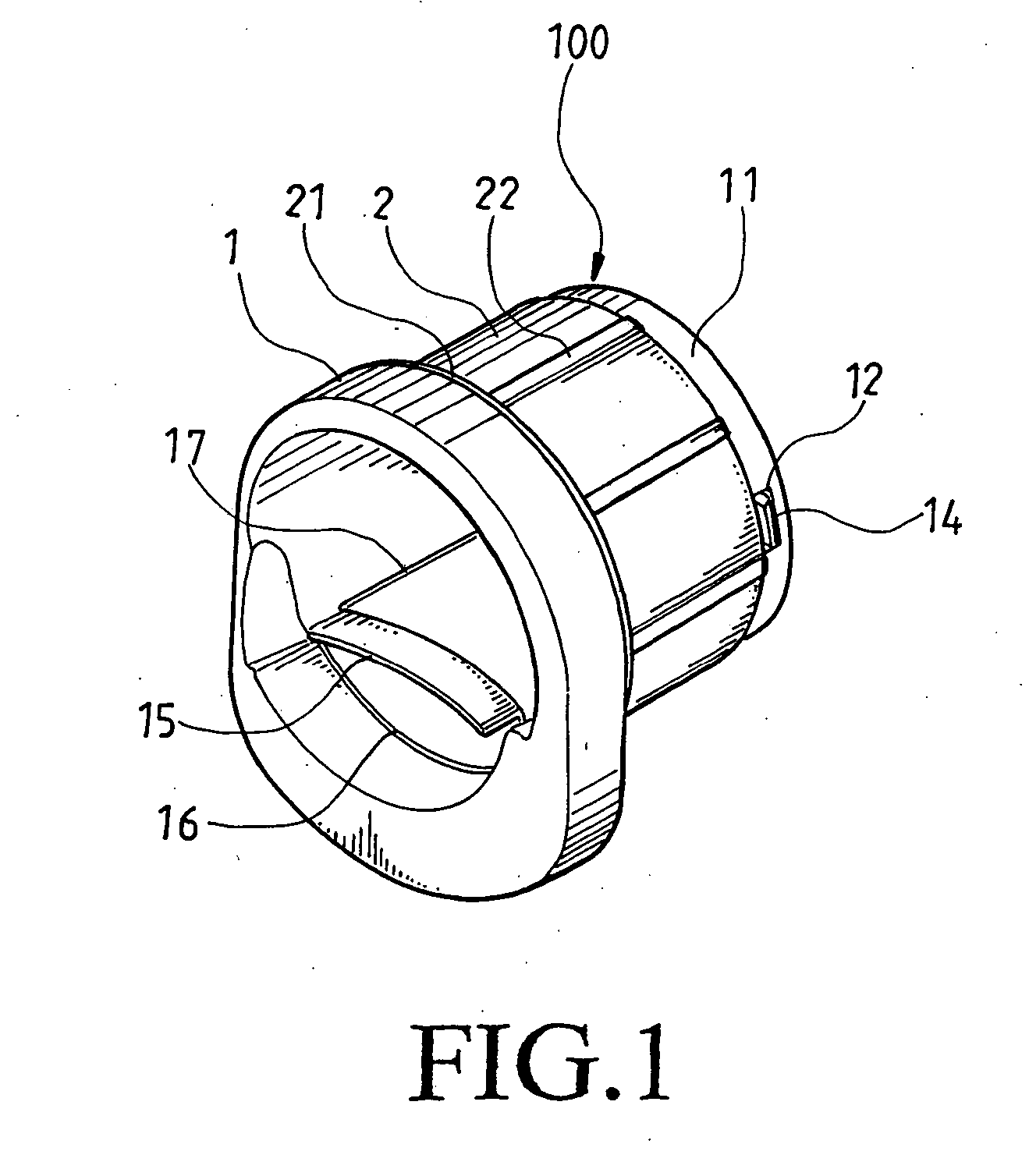
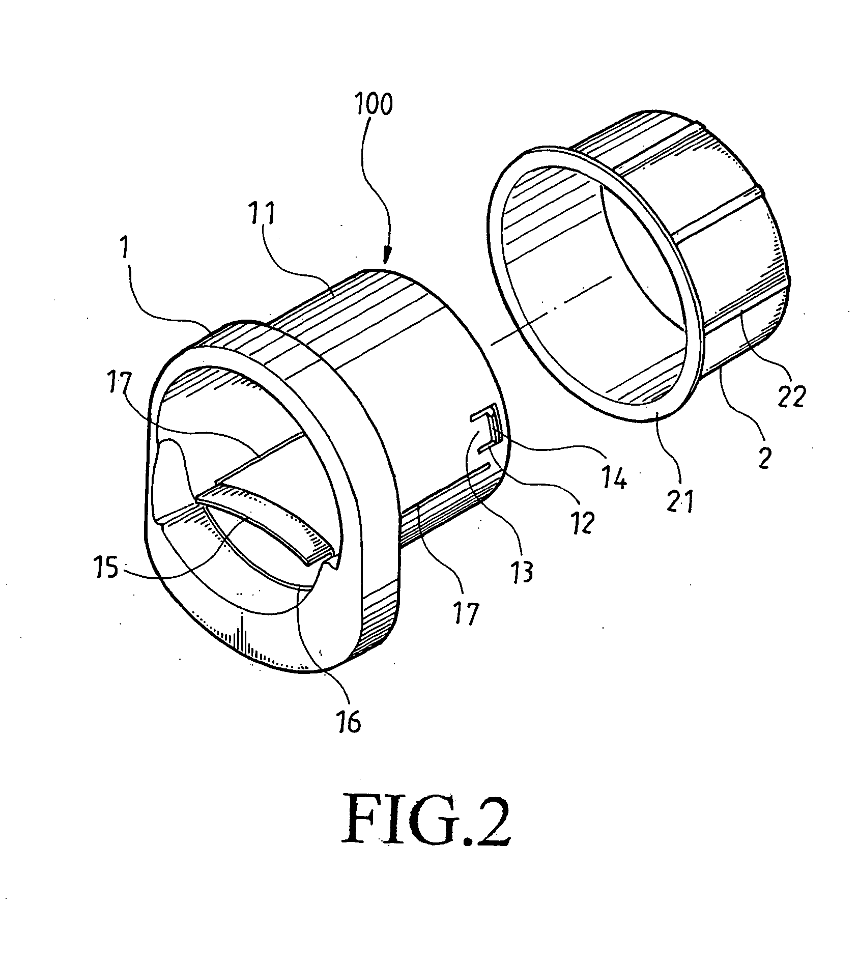
[0013] Please refer to FIGS. 1 and 2 that are assembled and exploded perspective views, respectively, of a hub for rolled wrap 100 according to an embodiment of the present invention, and to FIG. 3 that is a sectioned side view of the present invention. For the purpose of concision, the hub for rolled wrap 100 shall also be briefly referred to as the hub 100 throughout the specification. As shown, the hub 100 mainly includes a generally ring-shaped base 1 having a sleeve portion 11 axially extended from a rear side of the base 1 by a predetermined length, and a collar 2 having an inner diameter slightly larger than an outer diameter of the sleeve portion 11 of the base 1 for rotatably mounting around the sleeve portion 11.

[0014] The sleeve portion 11 of the base 1 is provided at two diametrically opposite sides near a rear end thereof with two axially extended U-shaped grooves 12 to form two elastic tabs 13. Free ends of the elastic tabs 13 are formed into two triangular ribs to fu...


PUM


Abstract

A hub includes a ring-shaped base having a sleeve portion axially extended from a rear side thereof, and a collar rotatably mounted on the sleeve portion. An L-shaped curved holding-down plate is provided at a lower inner side of the base, and slits are formed at joints of the holding-down plate and the base and the sleeve portion to provide the holding-down plate with a certain degree of elasticity. The hub is fitted in an open end of a rolled wrap with the rotatable collar tightly contacting with a radially inner side of the rolled wrap. Normally, the rolled wrap can be freely rotated and outward pulled for packaging an article, and when the holding-down plate is depressed to push the sleeve portion against the collar, the rolled wrap is held in place and a user may tensely stretch the outward pulled wrap to smoothly and firmly wrap the article.

Description

FIELD OF THE INVENTION [0001] The present invention relates to a hub for rolled wrap, and more particularly to a hub fitted in an open end of a rolled wrap to allow a user to more conveniently and quickly pull out and tensely stretch the rolled wrap for firmly wrapping an article. BACKGROUND OF THE INVENTION [0002] When a rolled wrap is used to packaging an article, particularly a large-size article, a user usually has to pull out a length of the rolled wrap to wrap the article and then cut the wrap. To facilitate easy pull of the rolled wrap, the rolled wrap is usually mounted on a tubular member to rotate freely and be pulled outward. However, the outward pulled wrap must be tensely stretched to smoothly and firmly package the article. Since the conventional tubular member for rotatably holding the rolled wrap thereon does not include any means for holding the rolled wrap in place, it is uneasy for a user to tensely stretch the outward pulled portion of the rolled wrap to tightly ...

Claims


Application Information

Patent Timeline
Patent Type & Authority Applications(United States)
IPC IPC(8): B65H75/28
CPCB65H16/06B65H23/08B65H75/185
Inventor HUA, WEI-HSIU
Owner HUA WEI HSIU
Why Eureka
Try Eureka