
Planar monopole antenna

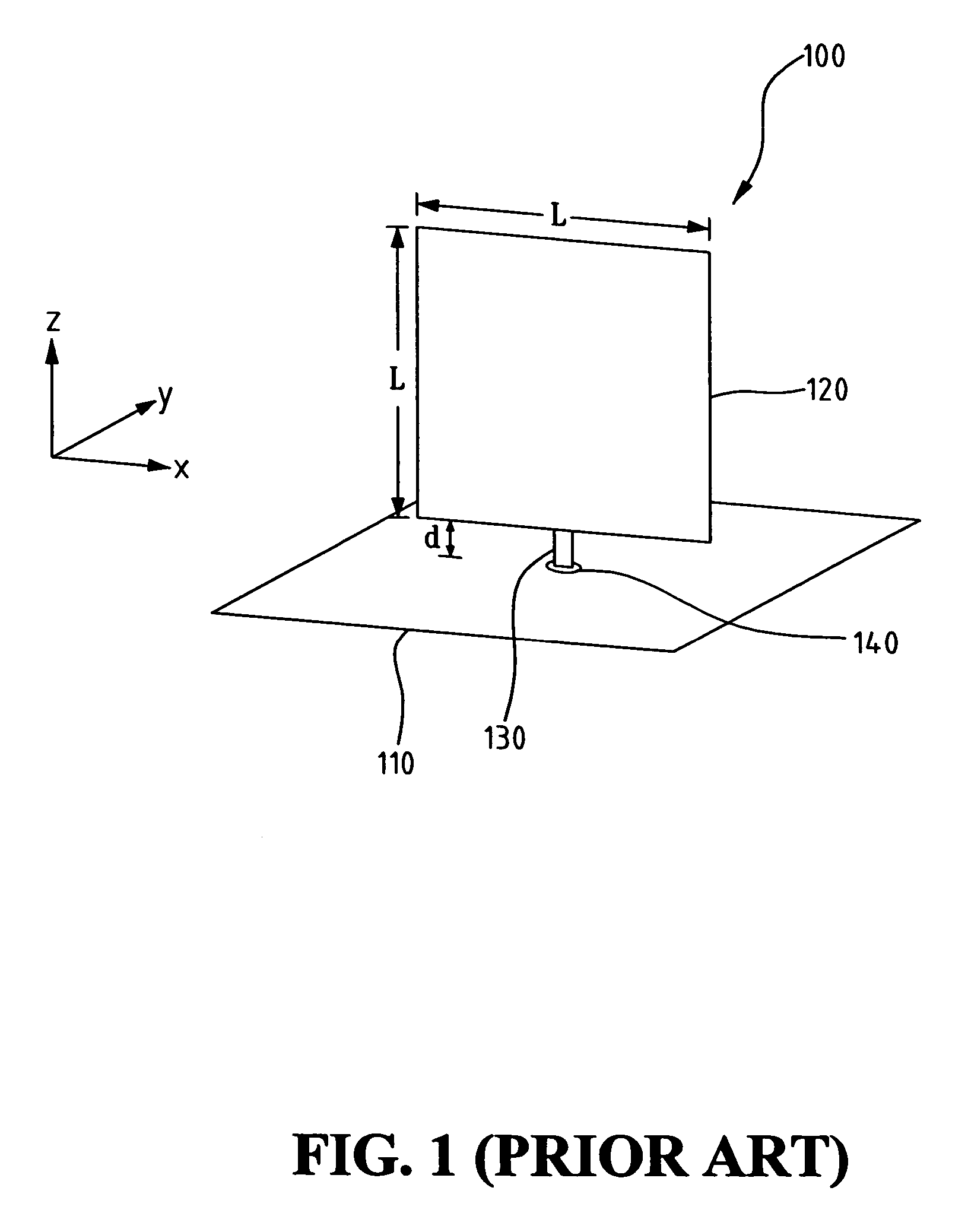
a technology of monopoly antenna and planar antenna, applied in the direction of resonant antenna, elongated active element feed, radiating element structure, etc., can solve the problems of large size, large design volume, and design that does not meet ultra-wideband operation, and achieve the effect of improving the problem of insufficient bandwidth

Active Publication Date: 2006-08-10
IND TECH RES INST
View PDF6 Cites 19 Cited by
  • Summary
  • Abstract
  • Description
  • Claims
  • Application Information

AI Technical Summary

Benefits of technology

The present invention aims to address the limited bandwidth of conventional wideband monopole antennas. The technical effect of the invention is to provide a planar monopole antenna that can improve insufficient bandwidth to meet the needs of ultra-wideband operation.

Problems solved by technology

The technical problem addressed in this patent is the need for an ultra-wideband antenna design that has a frequency ratio exceeding 1:7.5 and a bandwidth of at least 2 GHz, while also minimizing cross-polarization radiation. Current wideband antennas, such as monopole antennas, logarithm periodic antennas, and so on, do not meet these requirements.

Method used


Image

  • Planar monopole antenna
  • Planar monopole antenna
  • Planar monopole antenna

Examples


Embodiment Construction

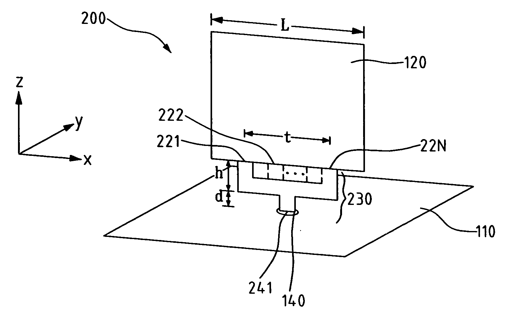
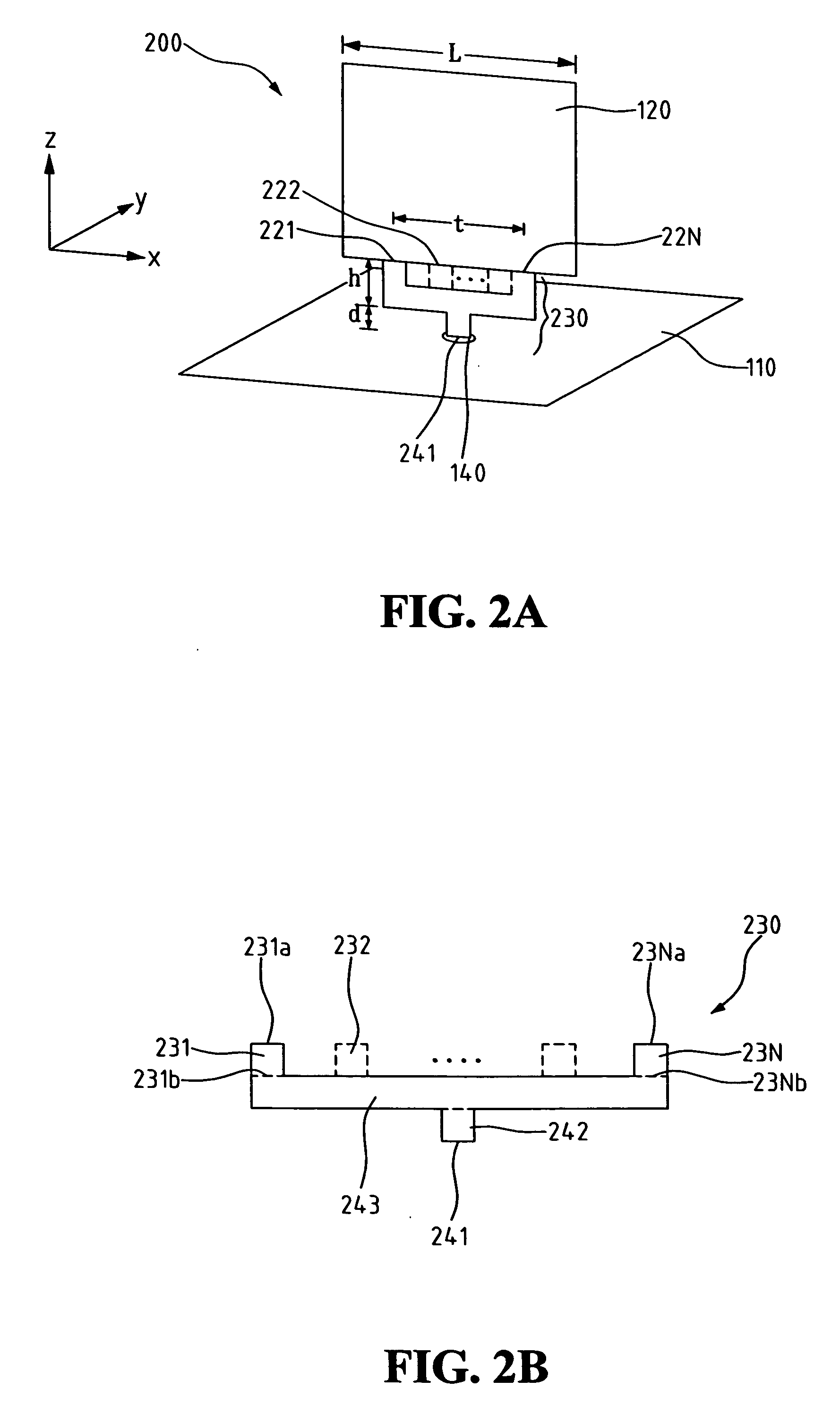
[0022]FIG. 2A shows a schematic view of the structure of a planar monopole antenna of the present invention. As shown in FIG. 2A, a planar monopole antenna 200 comprises a ground plate 110, a radiating metal plate 120 and a multi-branch feeding metal plate 230. Ground plate 110 has a via-hole 140. Radiating metal plate 120, located above ground plate 110, has a plurality of connection points 221-22N. Multi-branch feeding metal plate 230 is located between ground plate 110 and radiating metal plate 120, and is connected to radiating metal plate 120 with the plurality of connection points 221-22N. Multi-branch feeding metal plate 230 has a feeding point 241, and feeding point 241 is embedded into via-hole 140 of ground plate 110 and is electrically connected to a signal source (not shown).

[0023]FIG. 2B shows a schematic view of the structure of a multi-branch feeding metal plate of the present invention. As shown in FIG. 2B, multi-branch feeding metal plate 230 comprises a plurality ...


PUM


Abstract

A planar monopole antenna is provided. The planar monopole antenna comprises a ground plate, a radiating metal plate, and a multi-branch feeding metal plate. The multi-branch feeding metal plate is formed between the ground plate and the radiating metal plate, and has a single feeding point thereon. The radiating metal plate and the multi-branch feeding metal plate together can also be fabricated from a single metal plate by using a line-cutting or stamping technique, or formed on a same dielectric substrate by using a printing or etching technique. Thus, the planar monopole antenna is easy to construct at a low cost.

Description


Claims


Application Information

Patent Timeline
Owner IND TECH RES INST
Learn More