Tire parameter sensing system having a tire rotation dependent transmission scheme

a technology of transmission scheme and parameter sensing system, which is applied in the direction of tire measurement, vehicle components, transportation and packaging, etc., can solve the problems of low signal to noise ratio of parameter signal received by vehicle-based units, and the inability of vehicle-based units to accurately extract the sensed parameter

Active Publication Date: 2006-08-17
TRW AUTOMOTIVE US LLC +1
View PDF8 Cites 24 Cited by
  • Summary
  • Abstract
  • Description
  • Claims
  • Application Information

AI Technical Summary

Problems solved by technology

Additionally, when the tire-based unit is located at certain rotational positions relative to the vehicle, attenuation of the parameter signals may occur as the parameter signals pass through the structure of

Method used


Image

  • Tire parameter sensing system having a tire rotation dependent transmission scheme
  • Tire parameter sensing system having a tire rotation dependent transmission scheme
  • Tire parameter sensing system having a tire rotation dependent transmission scheme

Examples


Embodiment Construction

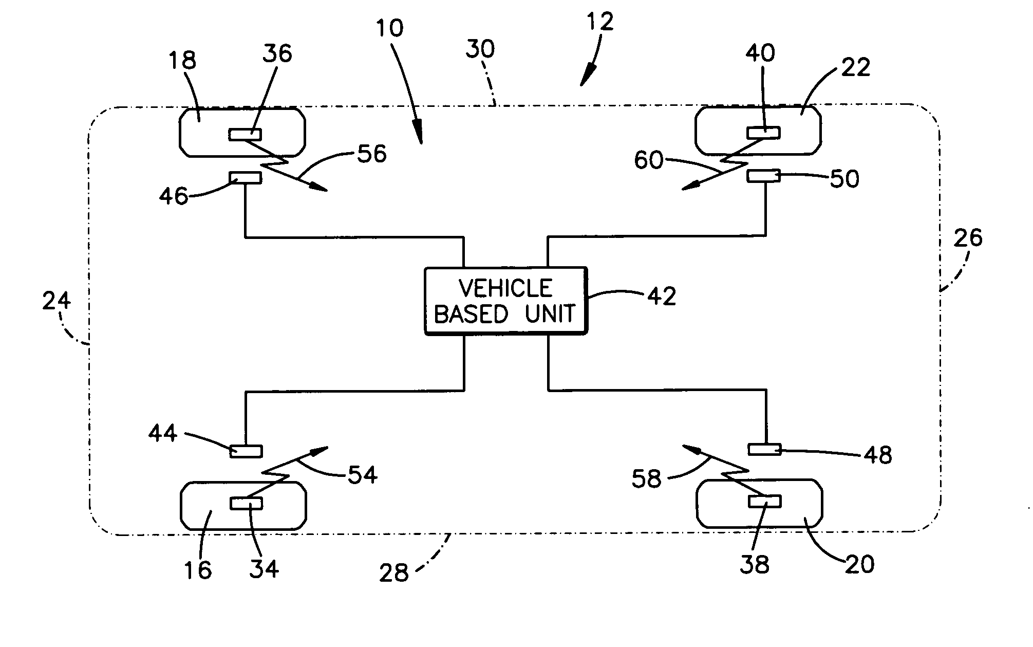
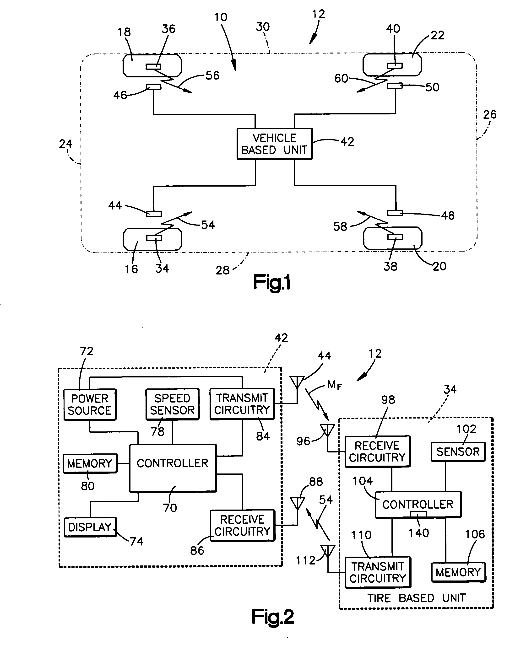
[0017]FIG. 1 schematically illustrates a vehicle 10 including a tire parameter sensing system 12 constructed in accordance with the present invention. For illustrative purposes, the vehicle 10 of FIG. 1 is an automobile having four tires 16, 18, 20, and 22. The present invention can be used with vehicles having a number of tires other than four.

[0018] The vehicle 10 has a front 24, a rear 26, and opposite left and right sides 28 and 30, respectively. FIG. 1 illustrates tire 16 at a front left corner location of the vehicle 10. Tire 18 is located at a front right corner location of the vehicle 10. Tire 20 is located at a rear left corner location of the vehicle 10 and tire 22 is located at a rear right corner location of the vehicle 10.

[0019] The tire parameter sensing system 12 includes four tire-based units 34, 36, 38, and 40, a vehicle-based unit 42, and four power transmitting antennas 44, 46, 48, and 50. Each tire 16, 18, 20, and 22 of the vehicle 10 includes an associated tir...


PUM


Abstract

A tire parameter sensing system (12) for a vehicle (10) comprises a vehicle-based unit (42) for receiving parameter signals. A tire-based unit (34) is associated with a tire (16) of the vehicle (10) and rotates with the tire (16). The tire-based unit (34) is located in a communication zone (134) for communicating with the vehicle-based unit (42) through only a portion of each rotation of the tire (16). The tire-based unit (34) is configured to sense a parameter of the tire (16) and to transmit a parameter signal (54) indicative thereof. The system (12) also comprises means (78) for monitoring the rotation of the tire and for providing rotation information indicative of the monitored tire rotation. The tire-based unit (34) is responsive to the rotation information for transmitting the parameter signal (54) while the tire-based unit (34) is located the communication zone (134).

Description

TECHNICAL FIELD [0001] The present invention relates to a tire parameter sensing system for a vehicle and to an associated method. More particularly, the present invention relates to a tire parameter sensing system and to an associated method in which a tire-based unit provides parameter signals to a vehicle-based unit according to a transmission scheme that is dependent upon tire rotation. BACKGROUND OF THE INVENTION [0002] Tire parameter sensing systems for vehicles typically include a plurality of tire-based units and a single vehicle-based unit. Each tire-based unit has an associated tire of the vehicle and is operable to sense at least one parameter of the tire. The sensed parameter(s) may include temperature, pressure, etc. Each tire-based unit is also operable to transmit a parameter signal indicative of the sensed parameter(s) to the vehicle-based unit. The vehicle-based unit is connected to a display. In response to receiving a parameter signal from a tire-based unit, the v...

Claims


Application Information

Patent Timeline
IPC IPC(8): B60C23/02
CPCB60C23/0408
Inventor LIN, XING PING
Owner TRW AUTOMOTIVE US LLC
Why Eureka
Try Eureka