
Tire and suspension warning and monitoring system

a monitoring system and suspension technology, applied in vehicle tyre testing, acceleration measurement using interia force, instruments, etc., can solve problems such as affecting handling performance, ten percent of tires that would normally wear out at 40,000 miles, and affecting steering and braking of vehicles, so as to eliminate higher-order frequency effects

Inactive Publication Date: 2008-10-28
TRW AUTOMOTIVE US LLC
View PDF40 Cites 20 Cited by
  • Summary
  • Abstract
  • Description
  • Claims
  • Application Information

AI Technical Summary

Benefits of technology

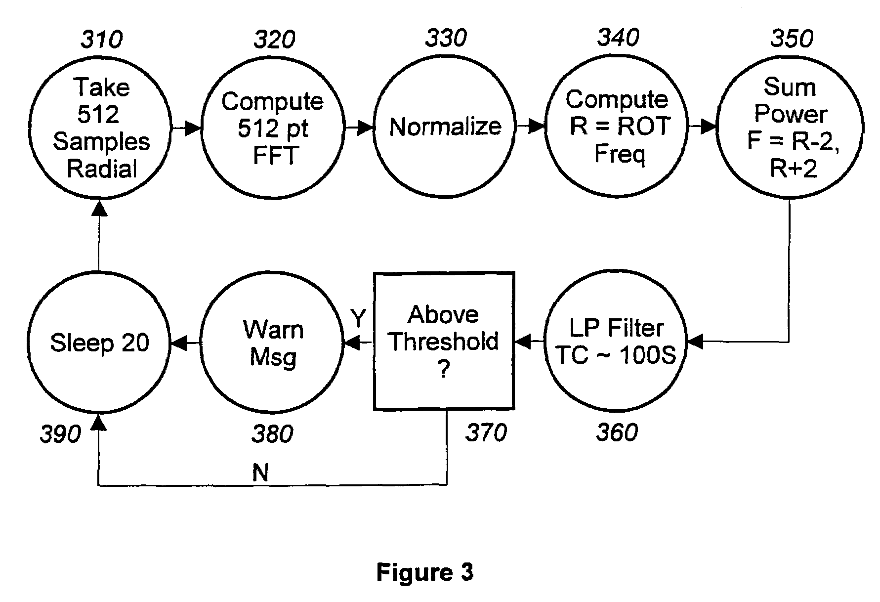
[0011]According to the present invention, at least one acceleration of the wheel is sensed before computing tire imbalance. A predetermined number of acceleration signal samples are collected and then transformed and normalized. The rotational frequency of the wheel is then computed from the transformed and normalized samples and the second harmonic of the rotational frequency is then computed. All of the frequency components are then summed around the computed...

Problems solved by technology

The handling performance of a motor vehicle, e.g., vehicle steering and braking, as well as fuel consumption, is affected by the condition of the tires and the suspension.
Handling performance can be affected by improper tire inflation, abnormal tire tread wear, out of balance conditions, as well as by poorly performing shock absorbers.
It is estimated that ten percent of tires that would normally wear out at 40,000 miles actually wear out at 30,000 miles due to abnormal tire tread wear.
While this system provides temperature and pressure information, it does not provide information about tread wear, balance and shock absorber performance.

Method used


Image

  • Tire and suspension warning and monitoring system
  • Tire and suspension warning and monitoring system
  • Tire and suspension warning and monitoring system

Examples


Embodiment Construction

[0022]Before beginning a detailed description of the subject invention, mention of the following is in order. When appropriate, like reference numerals and characters may be used to designate identical, corresponding, or similar components in differing drawing figures. Furthermore, in the detailed description to follow, example sizes / models / values / ranges may be given, although the present invention is not limited thereto. As a final note, well-known power connections and other well-known elements have not been shown within the drawing figures for simplicity of illustration and discussion and so as not to obscure the invention.

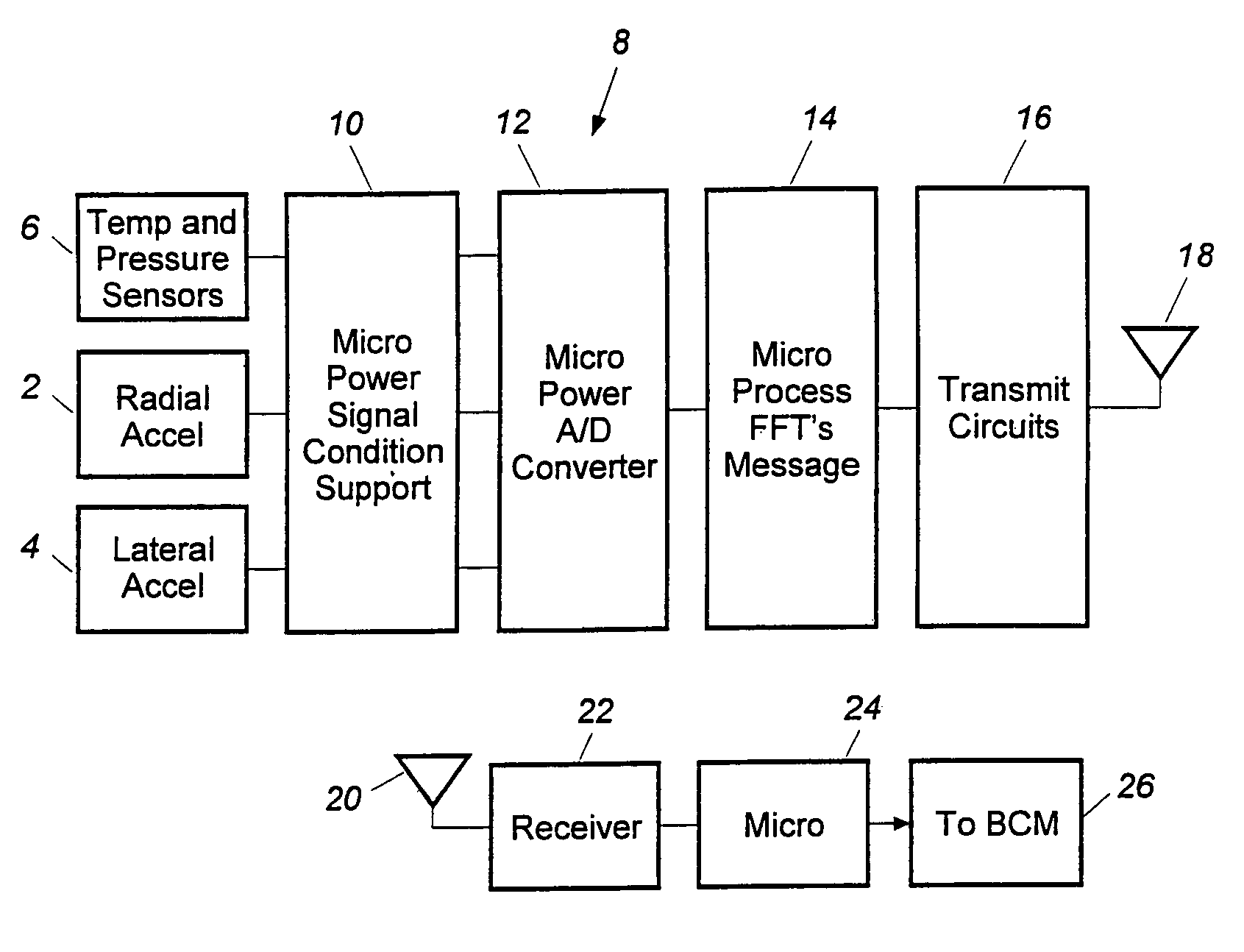
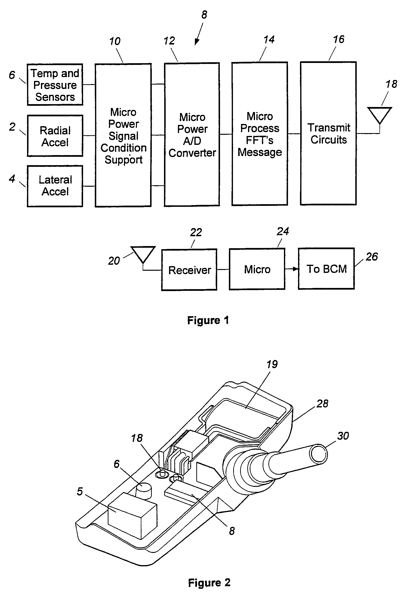
[0023]FIG. 1 is a block diagram of an example system capable of operating in accordance with the present invention. As shown in FIG. 1, one or more sensors are provided for sensing conditions at the vehicle wheel, either inside the tire or outside the tire on the wheel rim. At least one accelerometer 2 is provided for measuring an acceleration of the tire or wh...


PUM


Abstract

A tire and suspension monitoring and warning system consisting of a set of multi-function sensors that monitor and warn of a failure mode. The system monitors and warns for tire imbalance, tire tread wear, and shock absorbers for a tire attached to a vehicle. The monitoring and warning system includes one axial, radial, and lateral acceleration measurement of the wheel to provide acceleration signal sample power. For tire imbalance, signal sample power in the second harmonic of the tire rotational frequency is compared to that of the first harmonic. For tire tread wear, average signal sample power within a second frequency range is compared to a previously stored baseline value. For shock absorber performance, a sum of all frequency components in a second predetermined frequency range is compared to a baseline value.

Description

CROSS-REFERENCE TO RELATED APPLICATIONS[0001]The present invention is a divisional of U.S. patent application Ser. No. 09 / 900,324, filed Jul. 6, 2001 now U.S. Pat. No. 6,759,952 which is related to U.S. patent application Ser. No. 09 / 454,443, filed in the U.S. Patent and Trademark Office on Dec. 3, 1999 (now U.S. Pat. No. 6,278,361).BACKGROUND OF THE INVENTION[0002]The present invention relates to a tire and suspension warning and monitoring system that is composed of a set of sensors. These sensors monitor and measure current tire and suspension performance and periodically warn the driver when the tires or the suspension system needs servicing. There is one sensor for each tire on the vehicle. Each sensor measures the following tire and suspension performance (a) tire imbalance of each tire of a vehicle, (b) tire tread wear of each tire of a vehicle, and (c) shock absorber performance for each tire of a vehicle.[0003]The handling performance of a motor vehicle, e.g., vehicle steer...

Claims


Application Information

Patent Timeline
IPC IPC(8): B60C23/00G01P15/00B60C19/00B60C23/02G01M17/02G01M17/04G01P15/18
CPCG01M17/02G01M17/04Y10T152/10009
Inventor DUNBRIDGE, BARRYBROWN, KENNETH L.MCIVER, GEORGE W.MAGIAWALA, KIRAN R.CHILCOTT, KELLEY D.
Owner TRW AUTOMOTIVE US LLC
Learn More