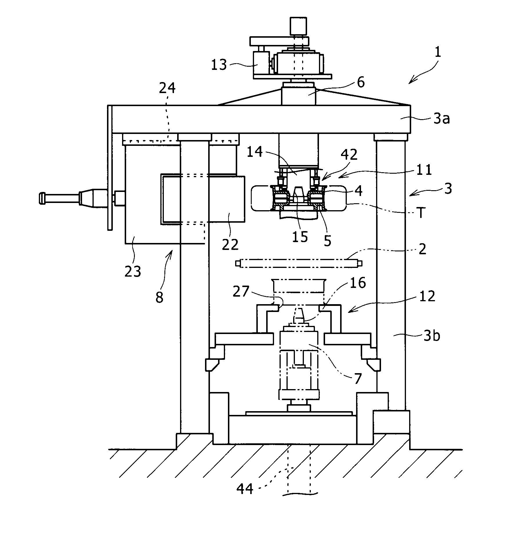
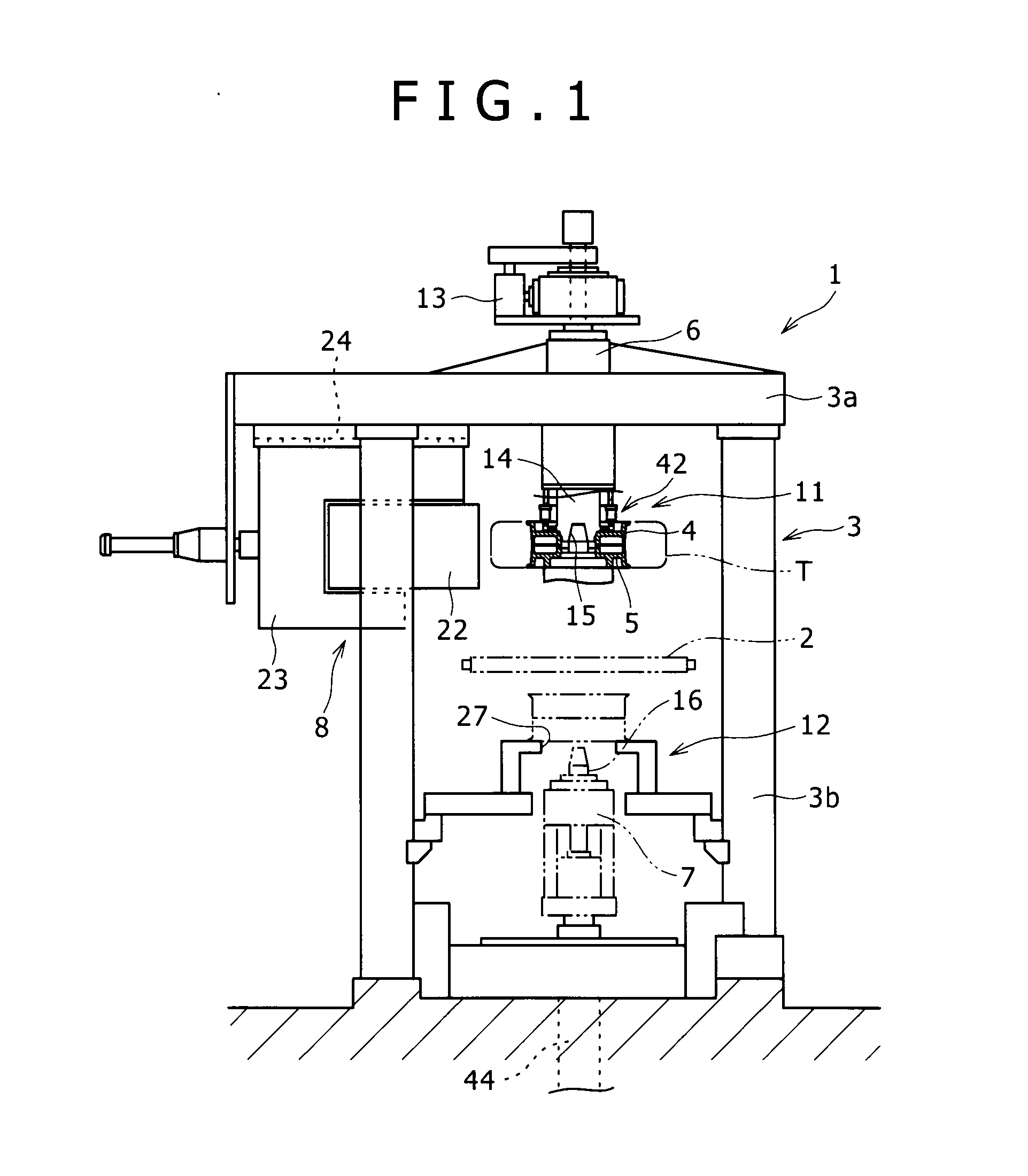
Rim mounting device for tire testing device, magnet mounting method, rim replacing device and tire testing device
a technology for rim replacement and tire testing, which is applied in vehicle tyre testing, instruments, roads, etc., can solve the problems of increasing device costs, affecting difficult maintenance, so as to avoid a decrease in the uniformity of measurement accuracy, easy detachment, and reliable fixation of even a heavyweight upper rim.
- Summary
- Abstract
- Description
- Claims
- Application Information
AI Technical Summary
Benefits of technology
Problems solved by technology
Method used
Image
Examples
first embodiment
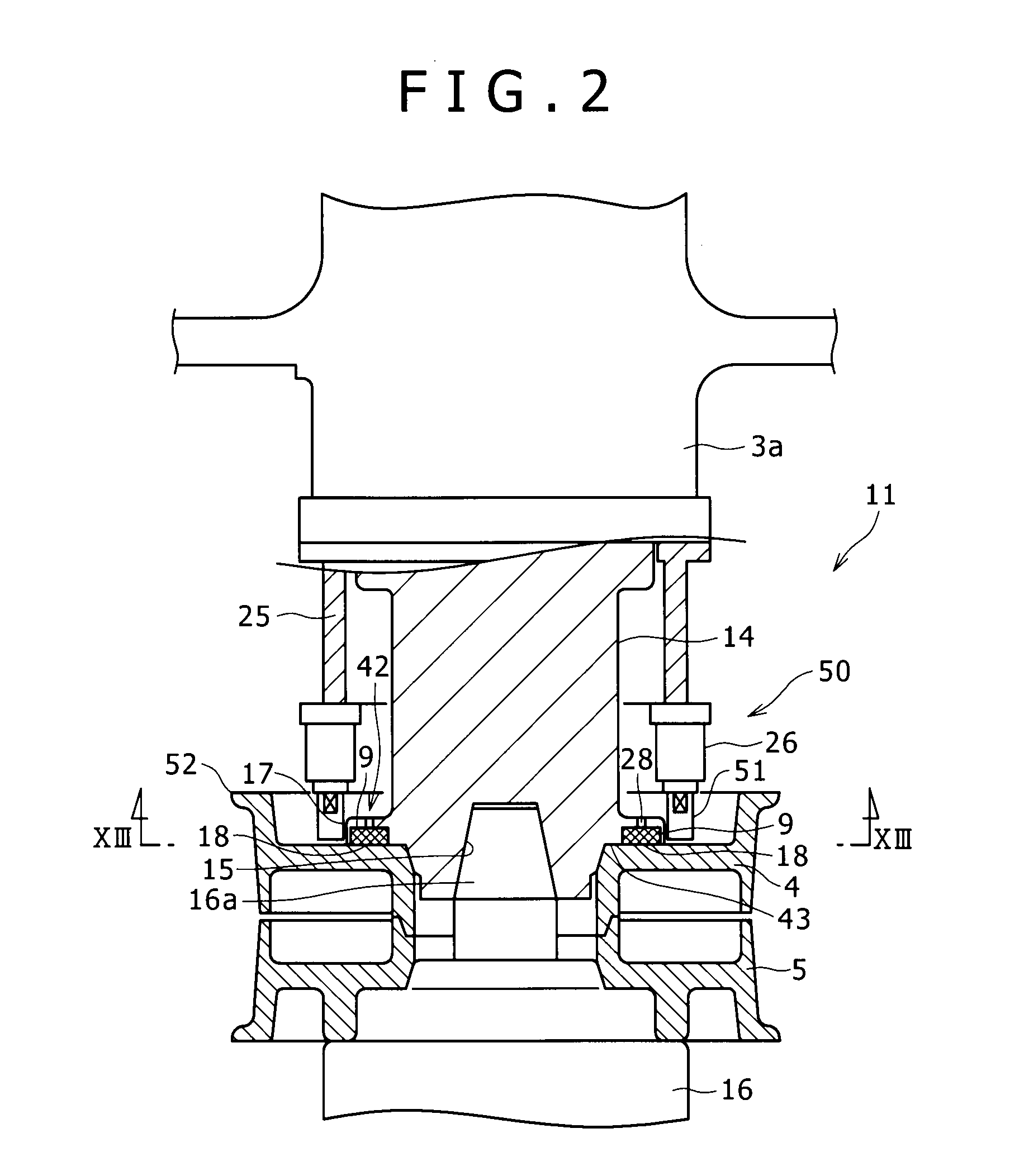
[0053]FIG. 5(a) shows the rim mounting device 42 according to a This rim mounting device 42 includes the flange 17 which represents a rim mounting section, a plurality of permanent magnets 9 which is respectively inserted inside the plurality of bottomed mounting recesses 18 formed in this flange 17, and a lid body 30 which corresponds to a scatter suppression member provided inside each mounting recess 18.
[0054]As shown in FIG. 4 which is a plan view of FIG. 5(a), the mounting recesses 18 are provided at a plurality of positions (in the present embodiment, 20 locations) on the upper rim mounting surface 43 in the upper spindle 14 so as to be arranged on a concentric circle centered around the axis of the upper spindle 14 and in a circumferential direction at constant intervals. The intervals between adjacent mounting recesses 18 do not necessarily have to be constant. However, the arrangement of these mounting recesses 18 at constant intervals equalizes the force the upper rim mou...
third embodiment
[0070]b) In the third embodiment, a through hole 28 is formed in the flange 17 to extend from an upper surface thereof (outside of the upper spindle 14) to the bottom surface 18a of the mounting recess 18 and it communicates with the inside of the mounting recess 18. The through hole 28 is in a linear shape vertically connecting the bottom surface 18a of the mounting recess 18 and the upper surface of the flange 17, and has a smaller pore diameter than the inner diameter of the mounting recess 18 and the outer diameter of the permanent magnet 9. A bar-shaped guide member 29, for instance, is inserted inside the through hole 28 from above, and the lower end of the guide member 29 is made to be contacted with the upper end of the case body 31, and thereby the through hole 28 makes it possible to slowly mount the permanent magnet 9 inside the mounting recess 18 while supporting the permanent magnet 9 against a force with which the bottom surface 18a of the mounting recess 18 attracts t...
fourth embodiment
[0072]FIG. 5(c) shows a case body 31 which is entirely constructed of one single member, however, the same advantages can be obtained even if this case body is divided into a bottom body which covers the bottom surface of the mounting recess 18 and a cylindrical body which opens upward and downward. In this case, the bottom body can be made of a magnetic material, and as a result, the same advantages as those in a fourth embodiment to be described later can be obtained.
[0073]The construction of the rim mounting device 42 according to the third embodiment, other than as described above, is the same as in the second embodiment, and therefore, further description thereof is hereby omitted.
[0074]FIG. 5(d) shows a rim mounting device 42 according to a fourth embodiment. This rim mounting device 42 differs from the device according to the first embodiment in that a bottom body 32 which covers the entire bottom surface is mounted on the bottom surface of the mounting recess 18. A through h...
PUM
 Abstract
Description
Claims
Application Information
 - R&D
- Intellectual Property
- Life Sciences
- Materials
- Tech Scout
- Unparalleled Data Quality
- Higher Quality Content
- 60% Fewer Hallucinations
Browse by: Latest US Patents, China's latest patents, Technical Efficacy Thesaurus, Application Domain, Technology Topic, Popular Technical Reports.
© 2025 PatSnap. All rights reserved.Legal|Privacy policy|Modern Slavery Act Transparency Statement|Sitemap|About US| Contact US: help@patsnap.com


