Electric hand power tool

Inactive Publication Date: 2006-08-17
ROBERT BOSCH GMBH
View PDF3 Cites 11 Cited by
  • Summary
  • Abstract
  • Description
  • Claims
  • Application Information

AI Technical Summary

Benefits of technology

[0005] Accordingly, it is an object of the present invention to provide an

Problems solved by technology

Thereby the material removed for example during longitudinal cutting covers the cutting line an

Method used


Image

  • Electric hand power tool
  • Electric hand power tool
  • Electric hand power tool

Examples


Example

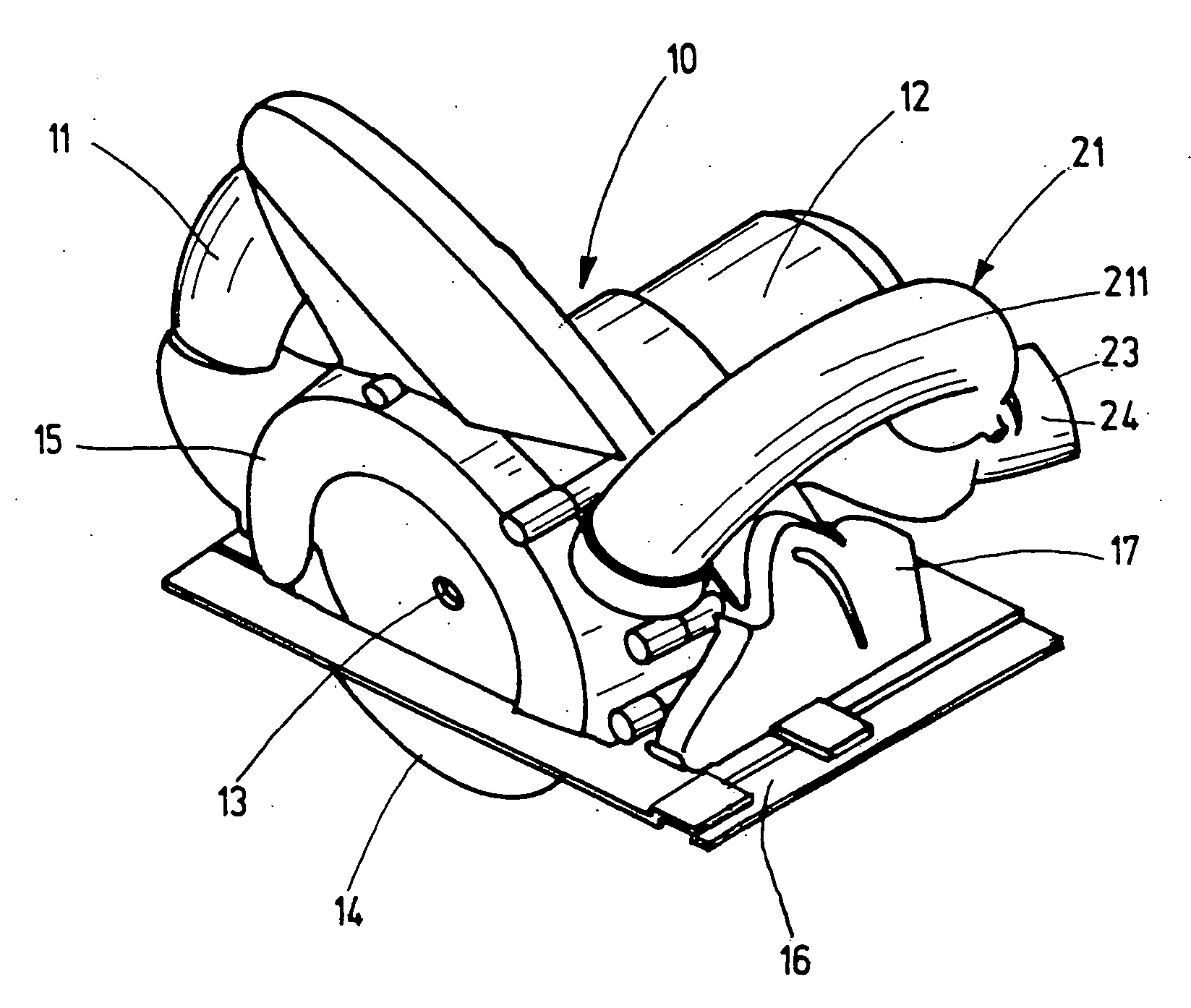
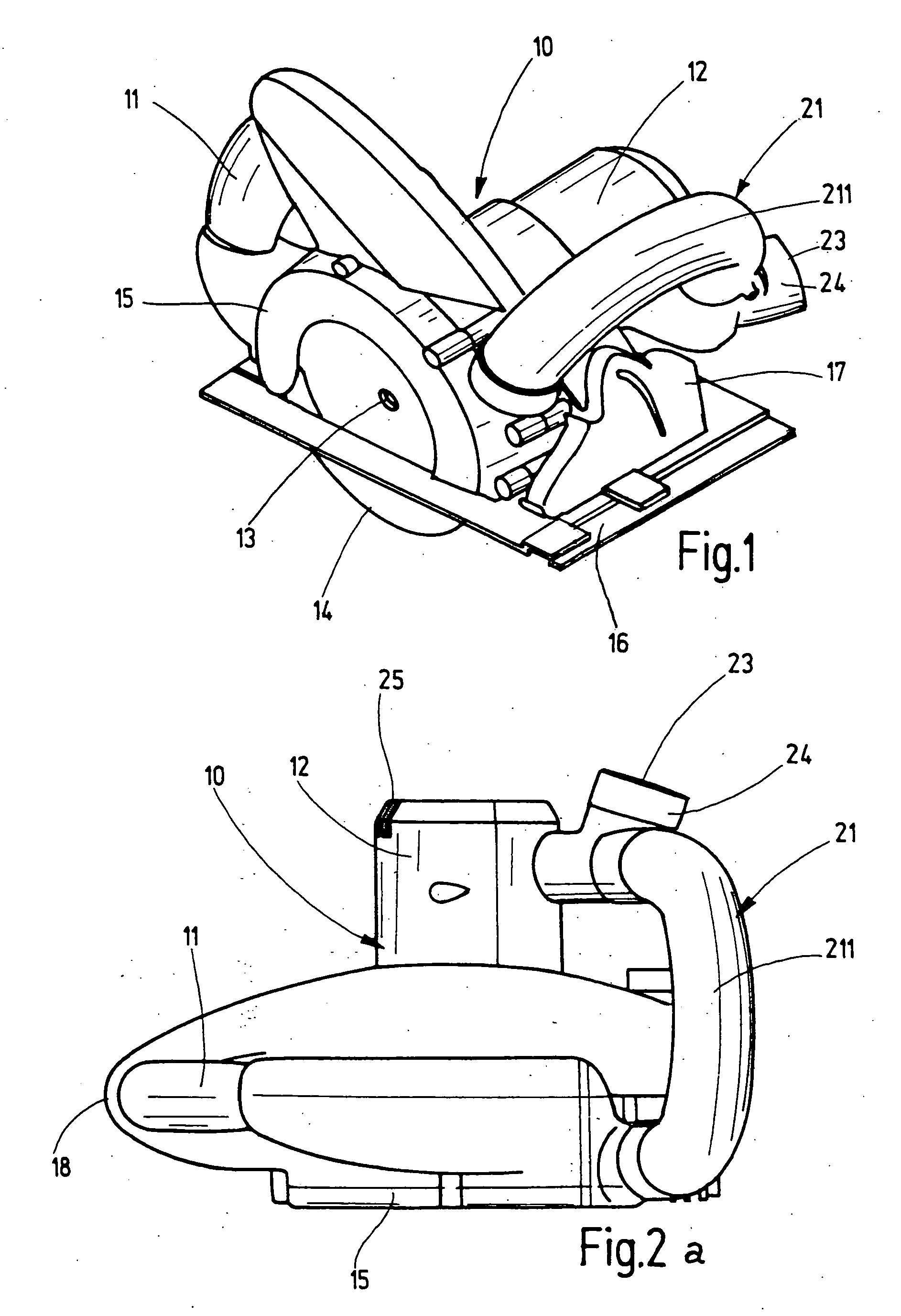
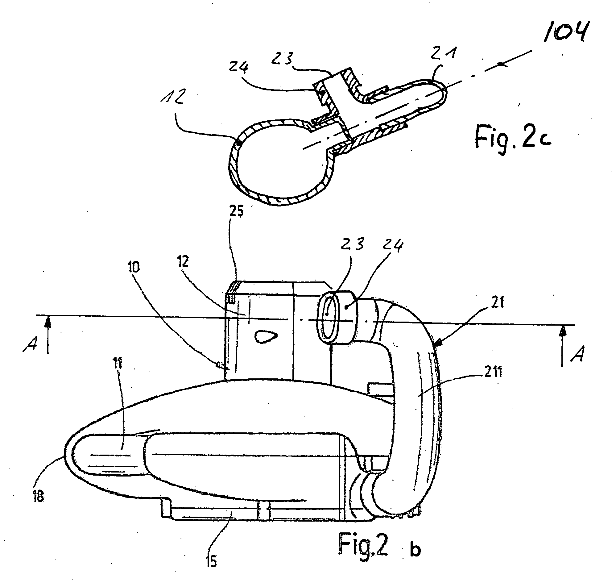
[0018] An electric hand circular power saw is shown in the drawings as an example for an electric hand power tool for chip-removing or grinding treatment of workpieces. It has a two-shell housing 10 with a handle 11 formed on it for guiding and handling of the power tool and with a motor housing 12 placed on it and accommodating an air-cool electric motor.

[0019] The electric motor drives a drive shaft 13 through a not shown one-stage transmission, and a saw blade 14 is mounted on the drive shaft. The circular saw blade 14 is covered in an upper region by a protective hood 15 which is screwed to the housing 10. The protective hood 15 extends to a support plate 16 which is connected with the machine housing 10. The support plate 16 is used for placing the power tool on the workpiece during a sawing process. The circular saw blade 14 extends through the support plate 16 and projects beyond it, downwardly more or less depending on a desired cutting depth.

[0020] For adjustment of the c...


PUM


Abstract

An electric hand power tool has a housing, a rotatably driven tool, a protective hood which at least partially covers the tool, a handle and an auxiliary handle for a two-hand guidance of the power tool, the auxiliary handle being hollow and formed as a withdrawal passage for a removed material thrown from the rotatably driven tool, the auxiliary handle having an inlet which is formed so that a radiating direction of the removed material from the rotatably driven tool is substantially tangential to a workpiece periphery in an inlet of the auxiliary handle, the inlet of the auxiliary handle being formed so that an inflow direction of the motor spent air coincides with the radiating direction of the removed material from the tool, and an air-cooled electric motor which drives the tool and is accommodated in the housing, the housing having an air passage provided with an air inlet opening for a motor spent air, the air passage being screw-shaped in direction of the motor spent air, which is directed in an opposite direction of the rotatably driven tool.

Description

CROSS-REFERENCE TO A RELATED APPLICATION [0001] This application is a continuation-in-part of patent application Ser. No. 10 / 719,752, filed on Nov. 21, 2003. [0002] Patent application Ser. Nos. 10 / 719,753 and 11 / 318,968 contain a subject matter which is similar to a subject matter of the present invention.BACKGROUND OF THE INVENTION [0003] The present invention relates to an electric hand power tool. [0004] In electric hand power tools with rotatable tools, such as a hand circular saw, wall chase cutter, stone saw, angle grinder, concrete grinder, plane, and the like, the material which is removed by the rotatable tool from the workpiece, for example chips or dust, is discharged from the protective hood directly into environment. Thereby the material removed for example during longitudinal cutting covers the cutting line and / or directly hits the operator, that significantly negatively affect the work with the machine. SUMMARY OF THE INVENTION [0005] Accordingly, it is an object of t...

Claims


Application Information

Patent Timeline
IPC IPC(8): B26D7/06B23D59/00B24B23/02B24B55/10B27B9/00
CPCB23D59/006B24B23/028B24B55/102B27B9/00Y10T83/202Y10T83/207
Inventor BOHNE, ULRICHHILD, EUGENROEHM, HEIKO
Owner ROBERT BOSCH GMBH
Why Eureka
Try Eureka