Shredder

Inactive Publication Date: 2006-08-17
ROYAL SOVEREIGN QINGDAO
View PDF5 Cites 38 Cited by
  • Summary
  • Abstract
  • Description
  • Claims
  • Application Information

AI Technical Summary

Benefits of technology

[0010] The present invention provides a shredder capable of reducing an operation time by allowing a large number of paper sheets to be cut into small pieces at the same time.
[0011] Moreover, another embodiment of the shredder of the pr

Problems solved by technology

Second, if a large number of paper sheets are fed at the same time, a driving motor may be stopped, or the paper sheets may not be completely shredded.
If an overload frequently occurs, a lifespan

Method used


Image

  • Shredder
  • Shredder
  • Shredder

Examples


first embodiment

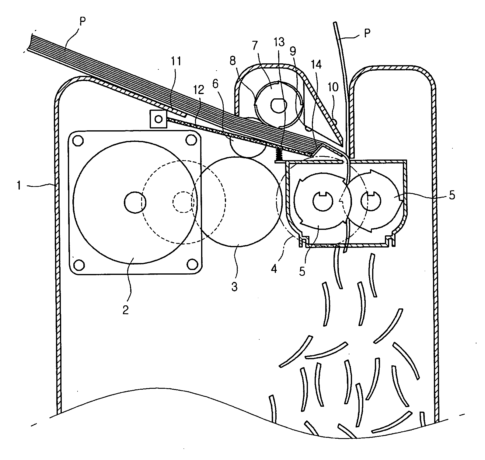
[0030]FIG. 1 is a cross-sectional view of a shredder according to a first embodiment of the present invention.

[0031] Referring to the embodiment illustrated in FIG. 1, the shredder according to the present invention can be characterized in that paper feeding can be controlled both manually and automatically.

[0032] Particularly, the shredder according to the present invention includes a case 1 forming an exterior of the shredder, a driving motor 2 formed inside the case 1 and providing a driving force, a connection part 3 transmitting a driving force of the driving motor 2 to a proper place, a cutter side connection gear 4 connected to the connection part 3 and transmitting a driving force to a cutter 5, and a feed side connection gear 6 connected to the connection part 3 and transmitting a driving force to an automatic paper feeding roller 7.

[0033] Particularly, an automatic feed side includes a paper feeding tray 11 on which a plurality of paper sheets are placed, a pressing par...

second embodiment

[0046] The second embodiment of the present invention is identical to the first embodiment except for the shape of the automatic paper feeding roller. Therefore, the same reference numbers will be used throughout the drawing to refer to the same or like parts as those in the first embodiment.

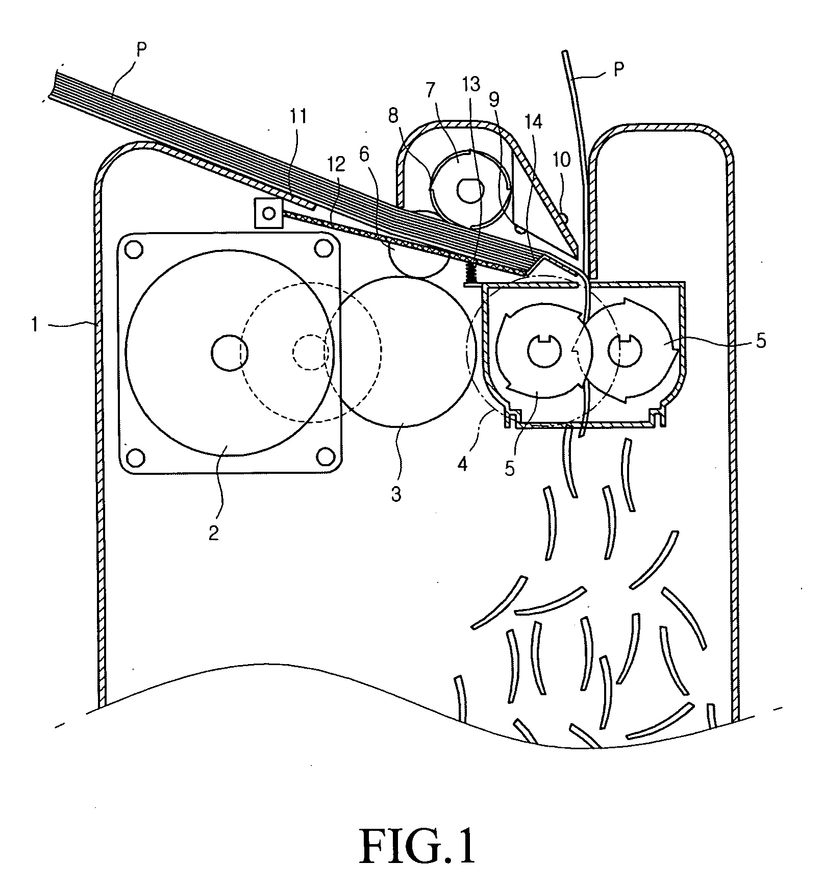
[0047]FIG. 2 is a front view of an automatic paper feeding roller according to the second embodiment of the present invention.

[0048] Referring to FIG. 2, in the present embodiment, provided are a plurality of automatic paper feeding rollers 7 for supplying paper sheets by certain amounts, a supply protrusion 8 formed near a central portion of each automatic paper feeding roller 7, and a roller shaft 15 for rotating the automatic paper feeding roller 7 at a constant speed. Although not shown, it is apparent to those skilled in the art that a gear engaged with the input side connection gear 6 is fixed to at least one side of the roller shaft 15.

[0049] In this embodiment of the present invention...

third embodiment

[0050] The third embodiment is identical to the first embodiment except for the automatic paper feeding roller for automatically supplying paper sheets. Therefore, the same reference numbers will be used throughout the drawing to refer to the same or like parts as those in the first embodiment.

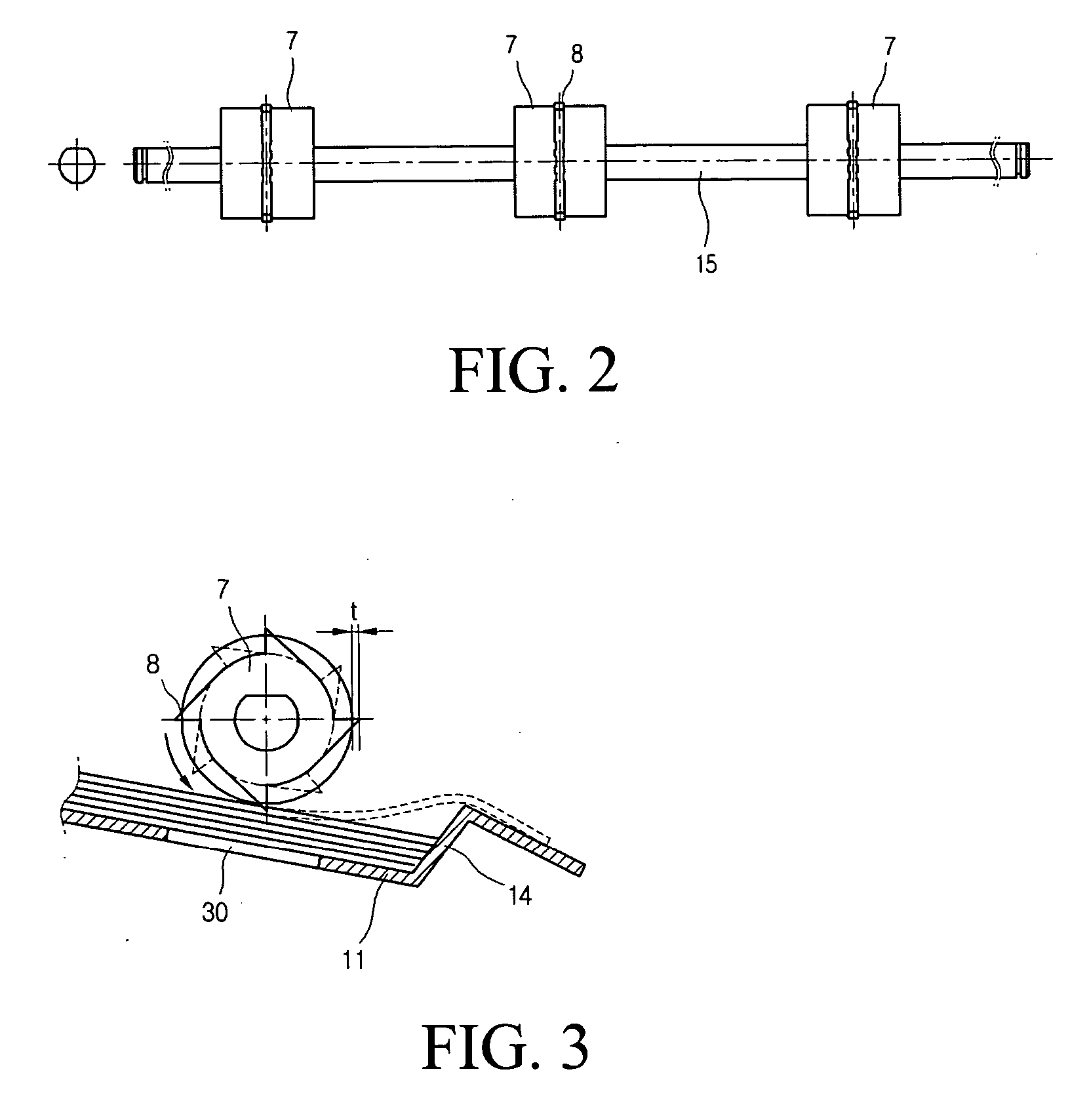
[0051]FIG. 3 is a cross-sectional view of an automatic paper feeding roller according to the third embodiment of the present invention.

[0052] Referring to FIG. 3, the automatic paper feeding roller 7 is formed as a circular shape, and a plurality of supply protrusions 8 are formed around an outer circumference of the automatic paper feeding roller 7. The supply protrusion protrudes outward to a certain length. Paper sheets (P) placed on the paper feeding tray 11 are simultaneously conveyed in plurality only when caught by the supply protrusion 8 and pass over the stepped protrusion 14. When the paper sheets caught by the supply protrusion 8 are conveyed, they are pushed in contact with an ou...


PUM

PropertyMeasurementUnit
Forceaaaaaaaaaa
Circumferenceaaaaaaaaaa

Abstract

A shredder is provided for allowing a user to select a desired feed type from a manual paper feeding type and an automatic paper feeding type. An embodiment of the shredder includes a driving motor; a connection part transmitting a dynamic force of the driving motor; a cutter shredding paper sheets inputted by a dynamic force transmitted from the connection part; a manual paper feeding part manually supplying paper sheets to the cutter; and an automatic paper feeding part automatically supplying paper sheets to the cutter by the dynamic force provided from the connection part.

Description

BACKGROUND OF THE INVENTION [0001] 1. Field of the Invention [0002] The present invention relates to a shredder, and particularly, to a shredder capable of improving user's convenience by allowing paper sheets to be selectively supplied automatically and manually. [0003] 2. Description of the Related Art [0004] A shredder is an office device, which is increasingly used. The shredder is an electronic device for cutting documents into small pieces in order to prevent the leakage of expired documents. [0005] The shredder may be divided into a manual paper feeding type and an automatic paper feeding type. Each type of shredder has its own advantages and disadvantages. The automatic feed type shredder is used to shred a large amount of paper sheets, and the manual feed type shredder is used to shred a small amount of paper sheets. [0006] The disadvantages of those types of shredders are as follows. First, as for the manual feed type shredder, an operator should stay close by during shred...

Claims


Application Information

Patent Timeline
IPC IPC(8): B02C1/08B26D7/00
CPCB02C18/0007B02C18/2283B02C18/2291Y10T83/222B02C4/02B02C4/42B02C18/06
Inventor PARK, HAN SUNGKIM, JONG GYU
Owner ROYAL SOVEREIGN QINGDAO
Why Eureka
Try Eureka