Furnace for vacuum carburizing with unsaturated aromatic hydrocarbons

a technology of unsaturated aromatic hydrocarbons and vacuum carburizing furnace, which is applied in the direction of furnaces, heat treatment equipment, manufacturing tools, etc., can solve the problems of uneven carburizing, inability to produce stress risers and change parts, etc., to achieve precise control and repeatability of the process

Inactive Publication Date: 2006-08-17
SURFACE COMBUSTION
View PDF28 Cites 4 Cited by
  • Summary
  • Abstract
  • Description
  • Claims
  • Application Information

AI Technical Summary

Benefits of technology

[0026] This object along with other features of the invention is achieved in a method or process for vacuum carburizing which is conventional in the sense that ferrous workpieces are heated to a carburizing temperature in a cleansed furnace pressure chamber that is maintained at a vacuum while a carburizing gas within the furnace chamber disassociates to produce carbon absorbed into the surface of the workpiece to produce carbon in solution and iron carbide, Fe3C. The improvement includes the steps of providing a source of an unsaturated aromatic hydrocarbon and a source of hydrogen. The unsaturated aromatic hydrocarbon is metered with a set quantity of the hydrogen to hydrogenate a substantial portion of the unsaturated aromatic into a naphthene hydrocarbon. The naphthene hydrocarbon is then metered into the furnace chamber proper as the carburizing gas along with any hydrogen not used in the hydrogenation reaction. It is believed that the stable carbon ring of naphthene in the vacuum environment of the furnace chamber minimizes carbon soot forming deposits while the ferrous surfaces of the workpiece function as a known catalyst to speed the cracking of the ring hydrocarbon so that the carbon in the naphthene molecules can be absorbed onto the surface of the workpiece in a manner not entirely dissimilar to the glow discharge of the ion process described above.
[0049] Still another aspect of the invention simply relates to an improved hydrogenation arrangement in which a liquid is pulsed by an injector and vaporized (by the vacuum from the furnace chamber) and the pulsed vapor, (momentum from the injector pulse) enhances the hydrogenation of the hydrocarbon, any hydrocarbon.

Problems solved by technology

For closely controlled, high stress areas such as required in the aerospace industries and even for gear trains in vehicular applications, the presence of metal oxides which, among other things, produce stress risers and change part dimensions is not acceptable.
(If the carburizing hydrocarbon gas is metered at less than carbon saturation potential, uneven carburizing occurs.)
Some limitations present in conventional vacuum furnaces relate to the ability to uniformly carburize parts having convoluted surfaces such as certain types of gears or certain parts which may be tightly packed in work baskets hindering penetration of the carburizing gases.
Like conventional vacuum carburizing, vacuum ion carburizing also has iron carbide network limitations since carbon diffuses into the surface until saturation.
This increases the expense of the furnace.
The first problem is that they have only been able to supply a level of carbon at saturation or above.
The high carbon potential is often rejected by many because carbide networks are typically formed which is undesirable.
This approach does work, but it is not truly desirable since the carbide networks are considered bad in most cases.
This requires extra maintenance and expense to keep the operation clean and reduces productivity.
In the one article cited, high quantities of hydrogen are introduced into the furnace, which could, in theory, raise repeatability issues.
This results because there is no way to control the carbon potential in the vacuum environment.
However, oxygen does not exist in a vacuum carburizing process and the vacuum drawn is constantly drawing out the carburizing gas.
For acetylene, the complications may be more severe.

Method used


Image

  • Furnace for vacuum carburizing with unsaturated aromatic hydrocarbons
  • Furnace for vacuum carburizing with unsaturated aromatic hydrocarbons
  • Furnace for vacuum carburizing with unsaturated aromatic hydrocarbons

Examples


Embodiment Construction

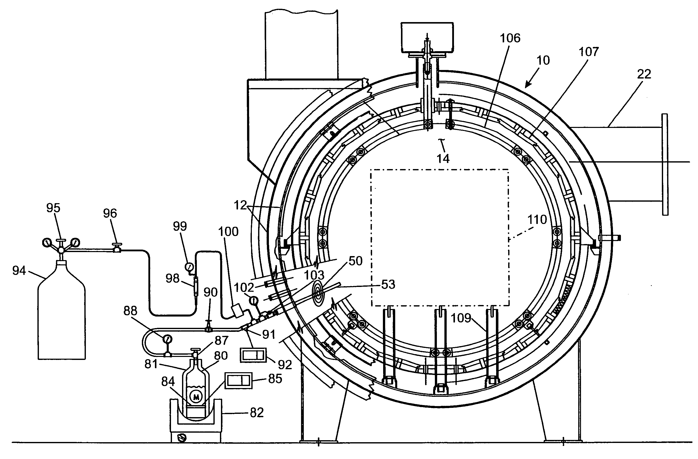
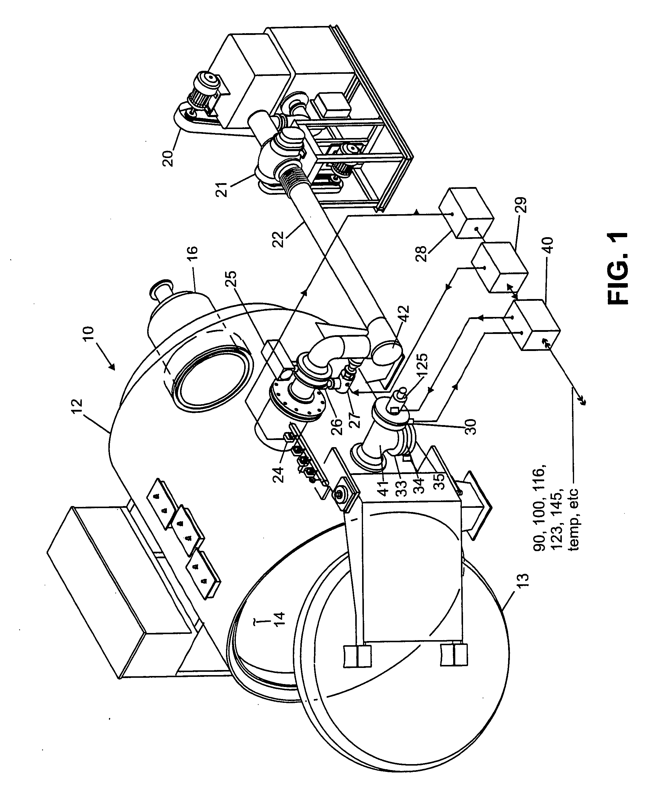
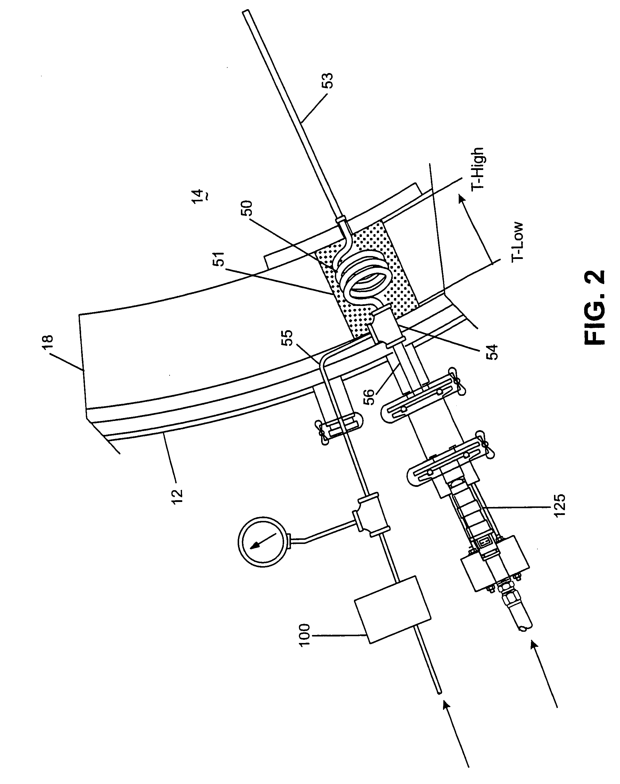
[0067] The Detailed Description of the Invention set forth below is for the purpose of illustrating preferred and alternative embodiments of the invention and is not necessarily for the purpose of limiting the invention.

[0068] A. The Hydrogenation and Carburizing Mediums.

[0069] Without wishing to be bound by any specific theory, and more particularly, without limiting the invention to any specific chemical theory, it is well known in the petrochemical field to hydrogenate aromatic hydrocarbons, particularly benzene is hydrogenated to cyclohexane. (See for example, U.S. Pat. No. 5,856,602 to Gildert et al., issued Jan. 5, 1999, entitled “Selective Hydrogenation of Aromatics Contained in Hydrocarbon Streams” and its related U.S. Pat. No. 5,773,670, entitled “Hydrogenation of Unsaturated Cyclic Compounds.”) Typically, a distillation process is used in the petroleum refinery field. However, gas phase hydrogenation is disclosed in U.S. Pat. No. 4,731,496 to Hu et al., issued Mar. 15, 1...


PUM

PropertyMeasurementUnit
temperatureaaaaaaaaaa
temperaturesaaaaaaaaaa

Abstract

Vacuum carburizing of ferrous workpieces is performed at low pressure in a vacuum furnace using an unsaturated aromatic such as benzene as the carburizing medium. The unsaturated aromatic is gas phase hydrogenated into naphthenes, such as cyclohexane, which is metered into the furnace chamber proper and functions as the carburizing gas. The furnace is constructed to be generally transparent to the naphthenes so that cracking tends to occur at the workpiece which functions as a catalyst to minimize carbon deposits. The unsaturated aromatic is supplied in liquid form to fuel injectors which inject the liquid aromatic as a vapor at duty cycles and firing orders to produce a uniform dispersion of the hydrocarbon gas about the work resulting in uniform carburizing of the workpieces. An in-situ methane infrared sensor controls the process. Excess hydrogen beyond what is required to hydrogenate the aromatic is added to the furnace chamber to either assure full carbon potential and produce methane or to perform variable carburizing. Hydrogenation occurs in a hydrogenation coil in fluid communication with the furnace chamber with temperature for the reaction set by the position of the hydrogenation coil in the furnace insulation.

Description

CROSS-REFERENCE TO RELATED APPLICATIONS [0001] This application is a divisional application of Ser. No. 10 / 205,721 filed Jul. 26, 2002, now allowed, which claims the benefit of U.S. Provisional Application No. 60 / 308,452, filed Jul. 27, 2001, entitled “Vacuum Carburizing by Unsaturated Aromatic Hydrocarbons” and also claims the benefit of U.S. Provisional Application No. 60 / 308,454, filed Jul. 27, 2001, entitled “Vacuum Carburizing by Saturated Aromatic Hydrocarbons.”[0002] This application also relates to an application, now U.S. Pat. No. 6,991,687, issued Jan. 31, 2006, entitled “Vacuum Carburizing with Naphthene Hydrocarbons” the disclosure of which is hereby incorporated herein and made a part hereof. [0003] This invention relates generally to method and apparatus for carburizing ferrous workpieces, and more particularly to method and apparatus for vacuum carburizing ferrous workpieces.BACKGROUND [0004] This invention (method and apparatus) relates to carburizing ferrous article...

Claims


Application Information

Patent Timeline
Patent Type & Authority Applications(United States)
IPC IPC(8): C21D1/74C21D1/773C23C8/22
CPCC21D1/773C23C8/22
Inventor POOR, RALPH P.BARBEE, GARY W.VERHOFF, STEPHEN H.BRUG, JAMES E.
Owner SURFACE COMBUSTION
Why Eureka
Try Eureka